Week 8 - Challenge 2 - Switch Bezel Design
Objective:
Create the Switch Bezel Plastic component through the given Class-A surface. To begin with, the tooling axis for the given Class-A Surface should be created meeting the requirements of the draft angle and at the end perform the Draft analysis on the model.
Take the Thickness of the component to be 2.5 mm.
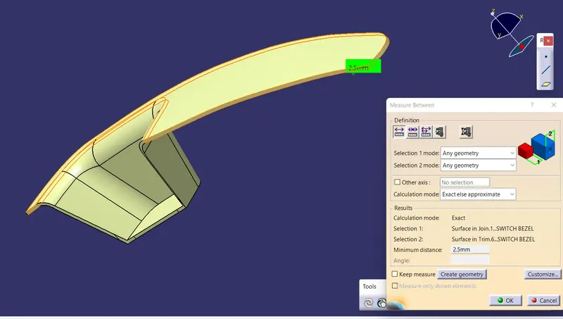
Tooling Axis Creation:
It is very important to create a tooling axis to decide the mold open and close sides. The tooling axis can be created by using the Bisecting Method. First we have to create a dummy tooling axis for our reference. Then we have to select the faces which might create a problem and create a intersetion line in the x and y directions. By using the two intersection lines or curves we can create the Bisecting Line in the x and y directions. After creating the two bisecting lines in the x and y direction then we can create the main tooling axis by creating a biseting line between the two lines.
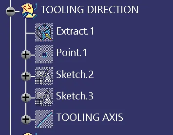
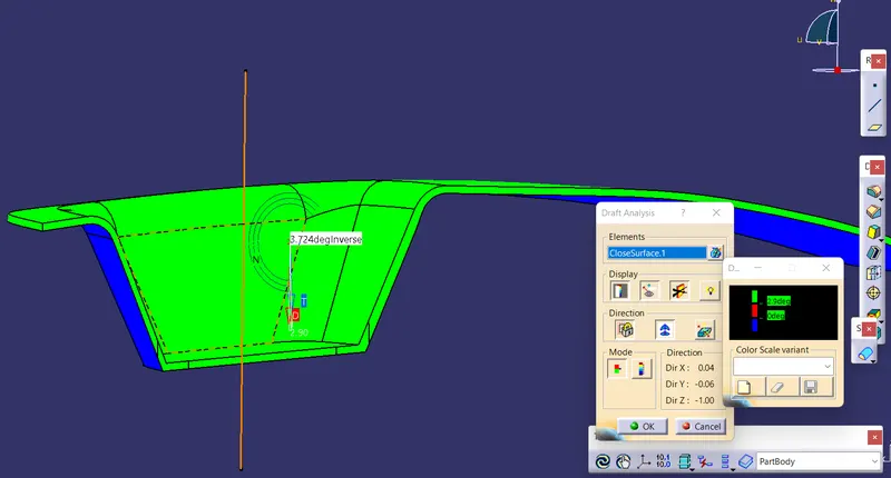
Draft Analysis Report:
Draft angle is nothing but providing a draft or tapper value to the part to improve the mold life cycle and easy removal of the product from the mold during the manufacturing. By creating draft angle we can increase the life of the molds and reduce the defects in products.
To ensure the draft we are doing draft analysis by crating a tooling axis. We can give draft angle between 0.5 to 3 degree. Mostly we are using 3 dergee draft.
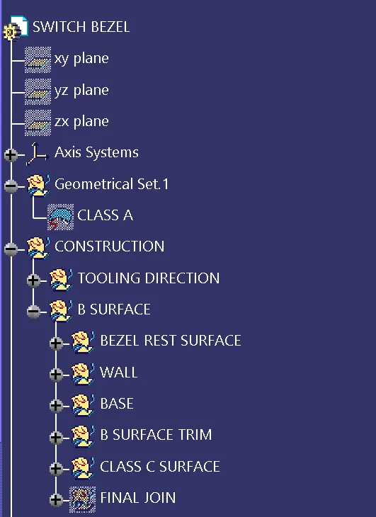
CLASS-B SURFACE CREATION:
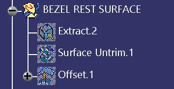
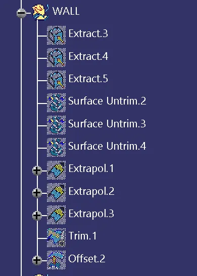
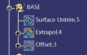
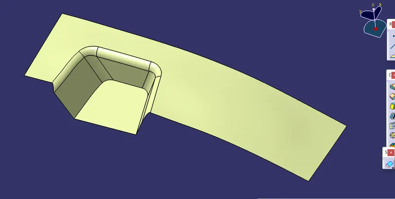
1. For creating the class - B surfcae the required surface except the offset surface have been extracted and then untrimmed all the surface.
2. Then all the surfaces have been extrapolated to get intersections between them.
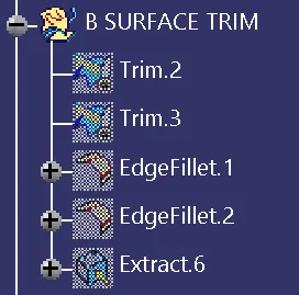
3. Since the thickness of the Switch bezel is 2.5 mm the B- Surface was offset to 2.5mm and the required trim operations must be carried out.
4. Finally, the required corners have been filleted 12.5mm ( 15mm-2.5).
CLASS-C SURFACE:
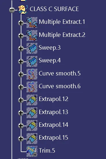
1. The requred outer edges of the A- surface were extracted using Multiple Extraxt. Then for avoiding the patches the curve is smoothened using the curve smooth option.
2. Then by using the sweep command the surface was created.
3. Then by using extrapolate command the edges were intersected between the surface corners which eases the trimming operation
4. Now the requred portion of the c - surface were trimmed out.
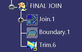
PUBLICATION:
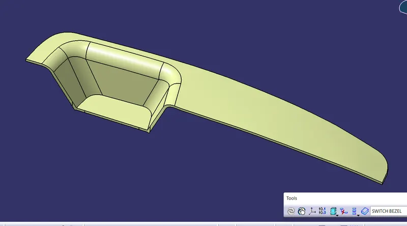
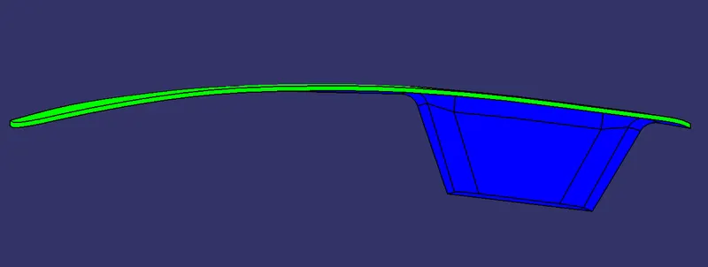
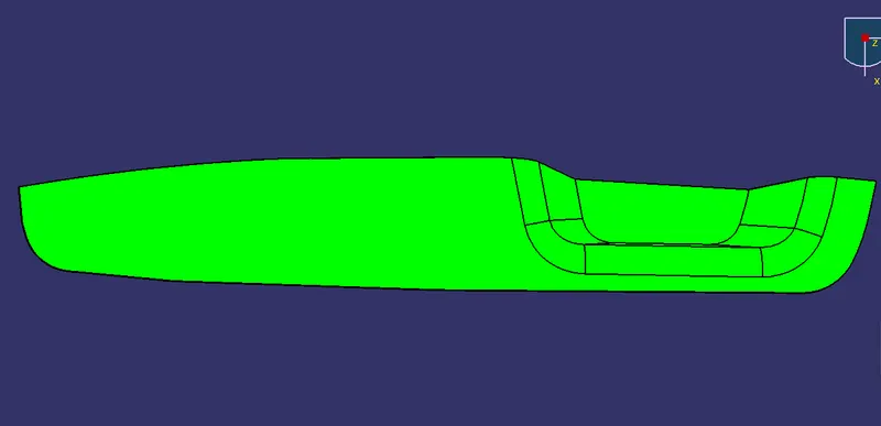
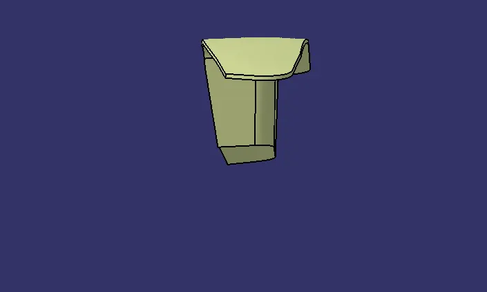
Solid model with the proper colour code of the draft angle in various orientations (Isometric, Front, Side, and Top View):
Isometric View
Front View
Top View Side view
Conclusion
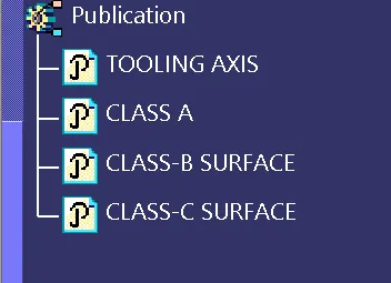
Finally the Class - A , B& C surfaces with the tooling direction have been publised and the switch bezel is moved on to the designing of the next operation of the creation of B - side features.