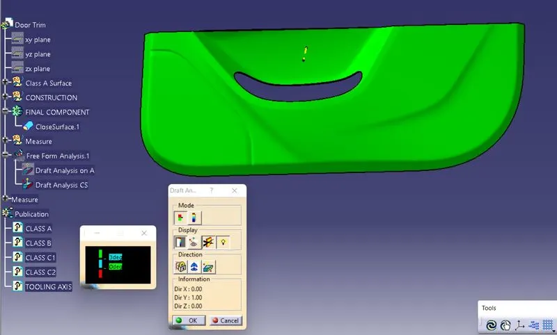
Week 8 - Challenge 5 - Door Trim Lower
AIM
To create the Door Trim Plastic component through the given Class-A surface.
REPORT
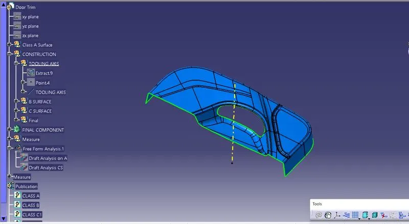
1. Creation of tooling axis
- Identify the best possible direction for creating the tooling axis.
- First extract the partiicular surface.
- Create a point on the centre of that surface.
- Draw a line normal to the surface passing through the point.
- That is our tooling axis.
2. Draft analysis on class A
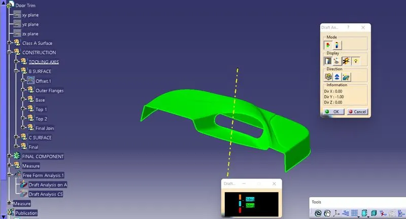
- Once the tooling axis is obtained, we conduct draft analysis on the class A surface with the help of tooling axis. This helps in determining weather the tooling axis we created is right or wrong.
- Click on the draft analysis option.
- Click on the compass icon and place the compass on the tooling axis.
- Click anywhwere on the surface to generate the analysis result.
- From the result it is clear that the surface has passed the draft analysis test.
3. Creation of B surface
- First offset the class A inwards by 2.5 mm.
- The offset surface can be seen with many patches.
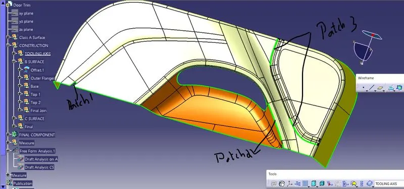
- We divide the offset surface into 4 regions namely Outer flanges, base, Top 1 and Top2.
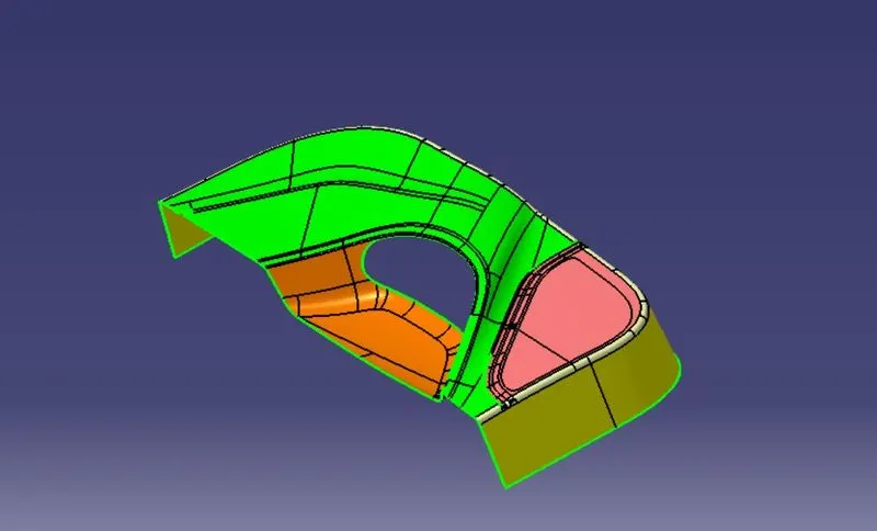
- Extract each surfaces one by one using multiple extract option and then using boundary, extrapolate them.
- Use other options like fill to fill certain patches.
- Use join to join the fill with the surface.
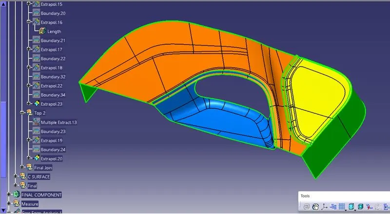
- Use the trim option to trim all these surfaces together.
- Apply edge fillets on all the sharp corners accordingly.
- B surface is thus created.
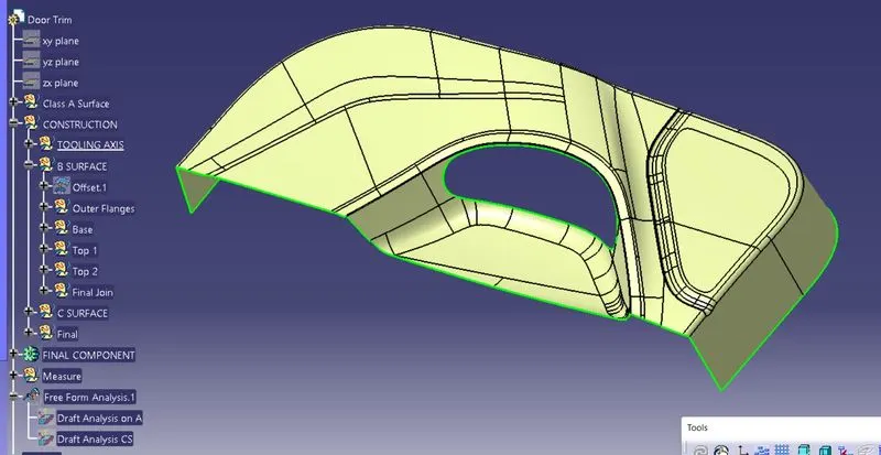
4. Creation of C surface
- Select the boundary option and select the outer boundary of Class A.
- Using sweep command sweep the surface for 90 degrees inwards
- Then select the inner boundary and repeat the same steps.
- We get both the C surfaces.
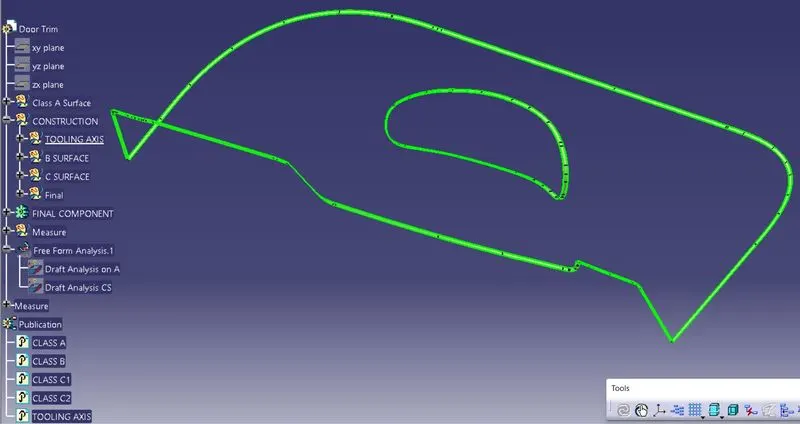
5. Final join
- First join Class A with both the C surfaces.
- Then using trim option, trim the A+C surface with B
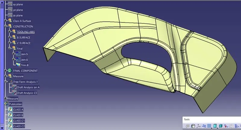
6. Creation of final component/closed surface
- Once the final join is complete, we open part design and select closed surface option.
- Click on the surface to create a closed surface.
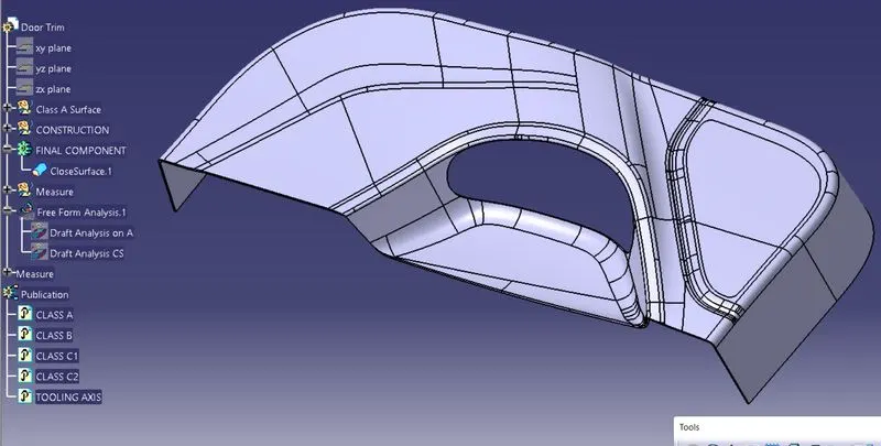
7. Draft Analysis on Closed Surface
- Follow the same procedure for draft analysis done on A for the finished component.
- From the results it is clear that the components passes the analysis.
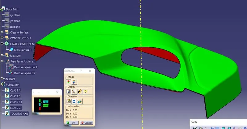
RESULT
1. ISOMETRIC VIEW
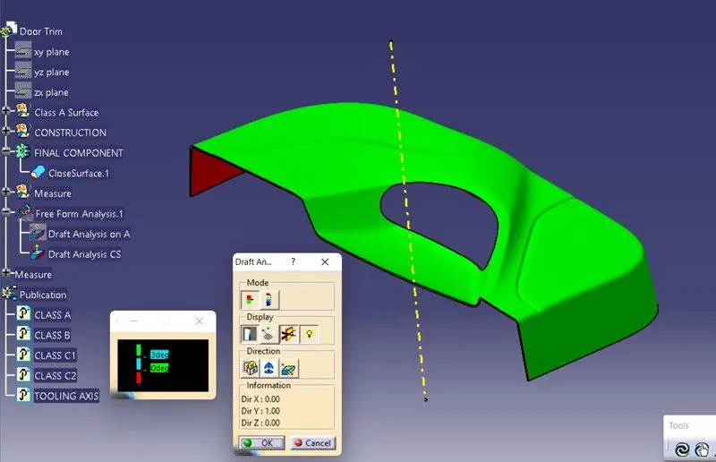
2. FRONT VIEW
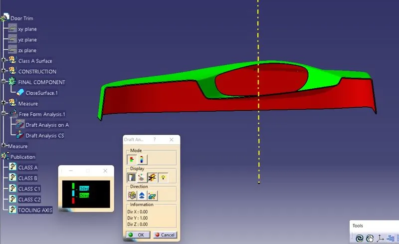
3. SIDE VIEW
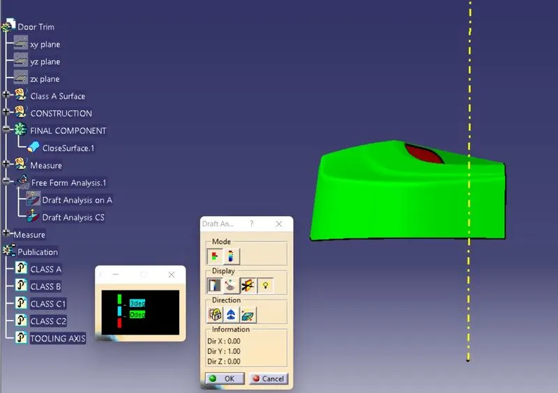
4. TOP VIEW