Week 8 - Challenge 5 - Door Trim Lower
Aim :
- To Create the Door Trim Plastic component through the given Class-A surface.
- Begin with the tooling axis for the given Class-A Surface.
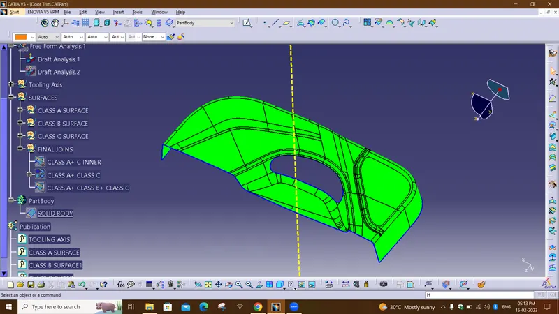
- Created Tooling axis should clear the draft analysis of class a surface and final solid body.
Take the Thickness of the component to be 2.5 mm.
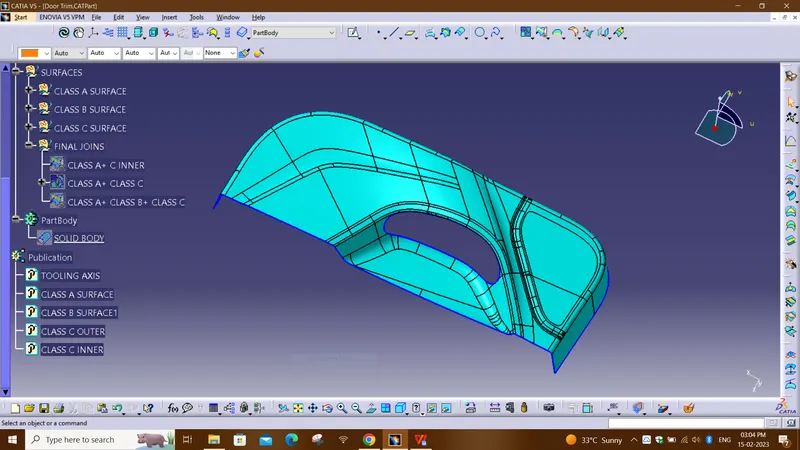
Given Class-A Surface :-
Determine Tooling Axis:
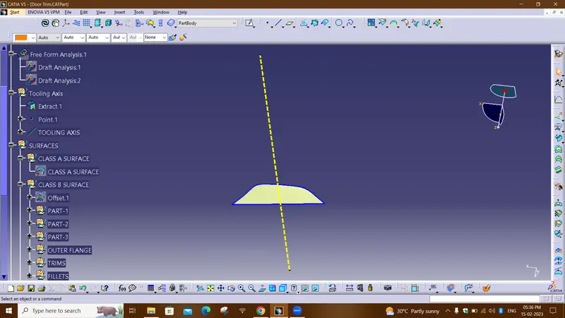
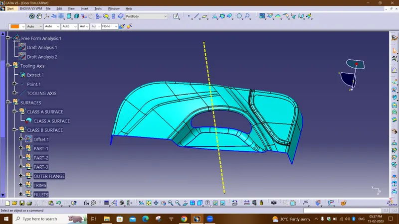
- Create a Tooling Axis along the best possible direction as per the Class A.
- In this model NORMAL TO SURFACE method is used for creating tooling axis.
- After creation of tooling axis publish the tooling Axis.
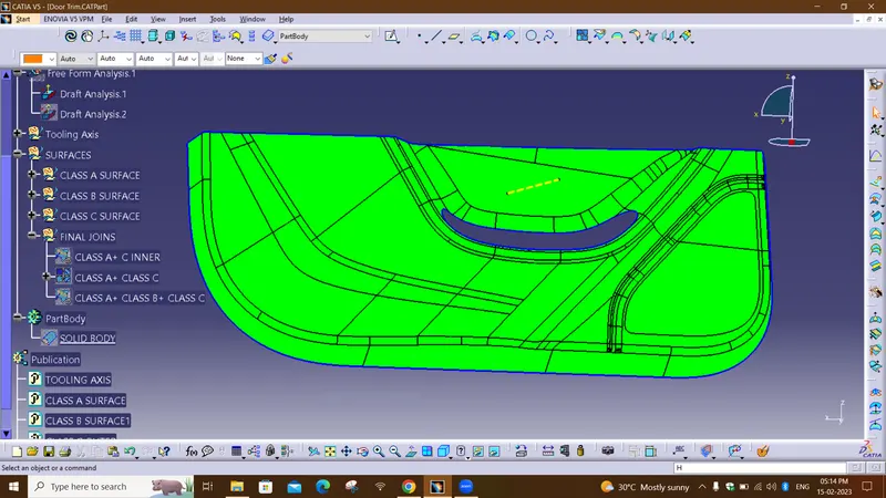
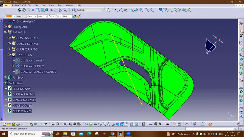
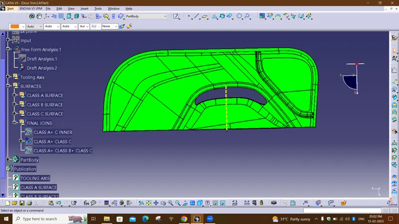
DRAFT ANALYSIS OF CLASS A SURFACE:
Change View Mode Customization to Material mode
Go to INSERT > ANALYSIS > FEATURE DRAFT ANALYSIS and move the compass to the Tooling Axis. Change the range to 3°. Apply the settings.
Uses the compass to define the new current draft direction.
Class B surface :
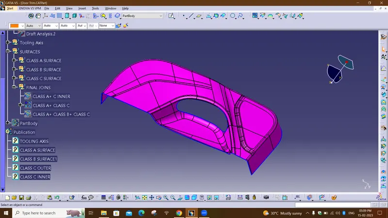
we offset the Class A surface and get the B surface body here we offset the 2.5mm value so we get the thickness is 2.5mm is mention in above so we offset the A surface for 2.5mm .
After the offset we get the surface but in that offset some patches of surface is missing so we required to solve it.
Class C Surface:
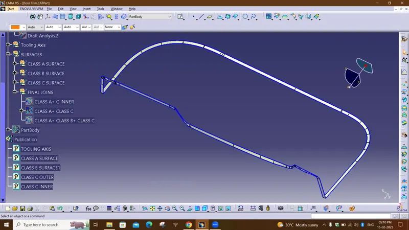
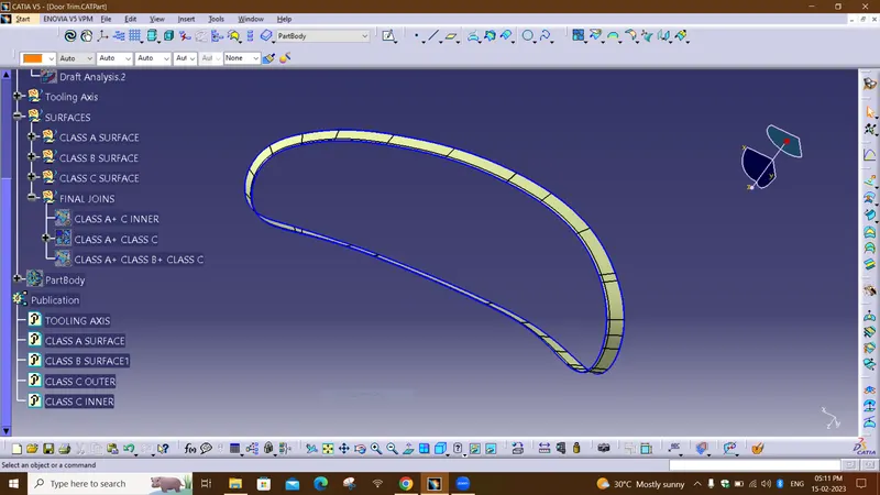
To create a Class C surface, first, extract the boundaries of the Class A Surface.
Now using the Sweep option create the surface. To perform this operation, Go to the Toolbar > Sweep > Profile type > Line > Subtype: With draft direction > Guide curve 1- (select the extracted boundaries) the in Draft direction (select the tooling axis) angle and length as 3° and 4mm respectively and click ok.
CLOSED SURFACE OR A+B+C SURFACE:
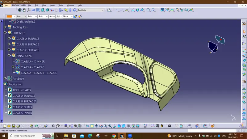
DIFFERENT VIEWS OF SOLID BODY:
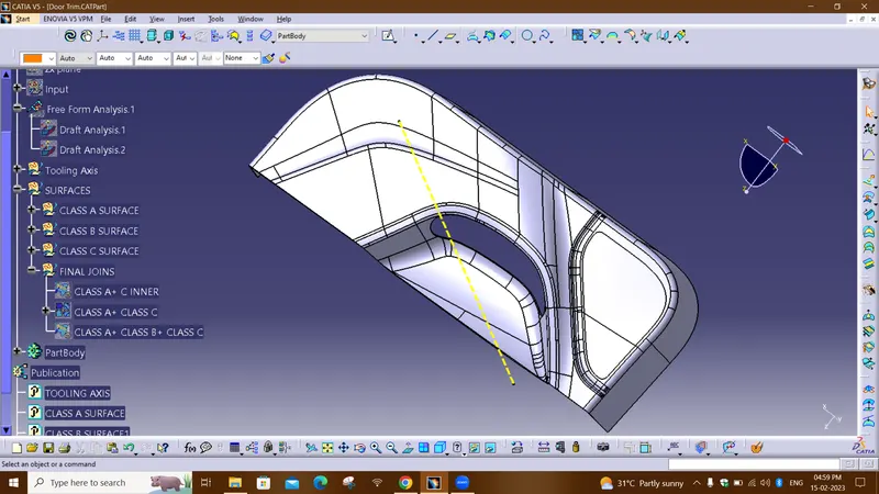
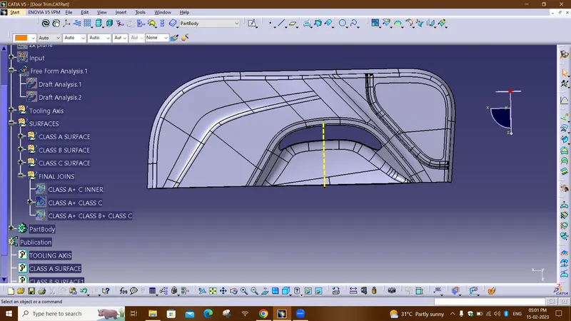
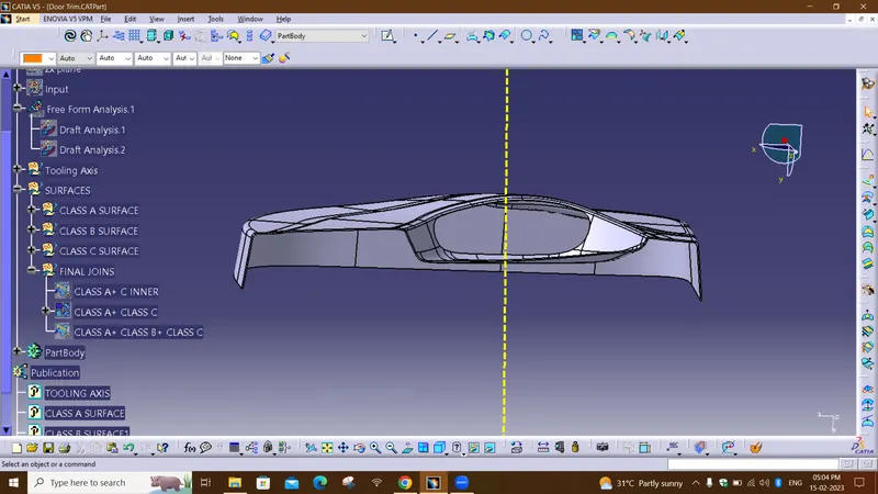
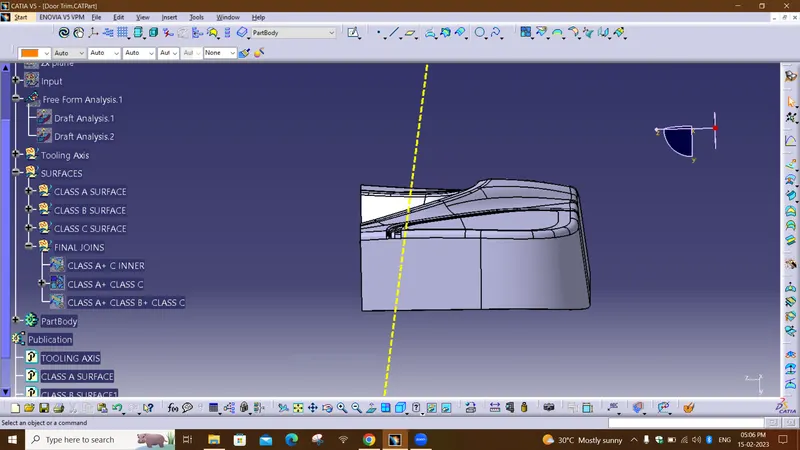
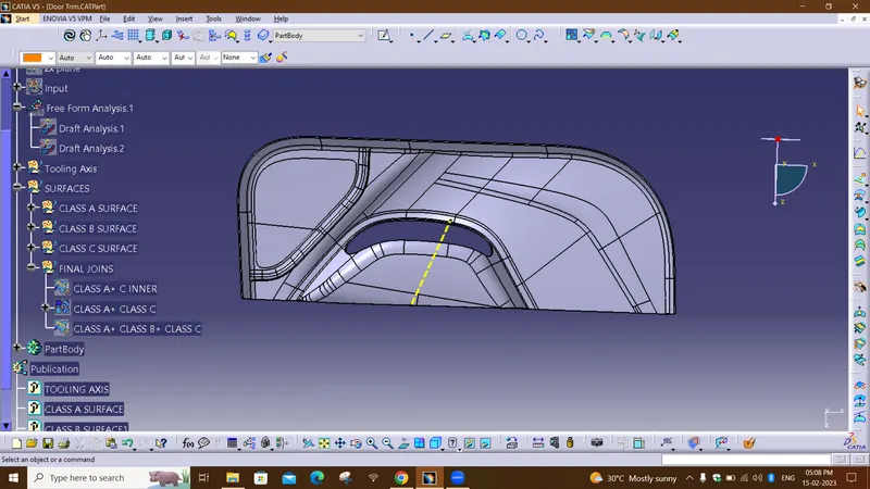
DIFFERENT DRAFT ANALYSIS VIEWS OF SOLID BODY:
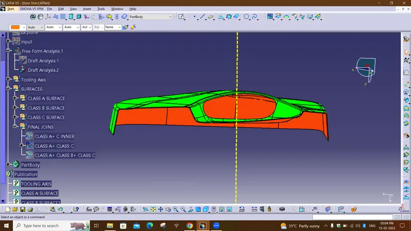
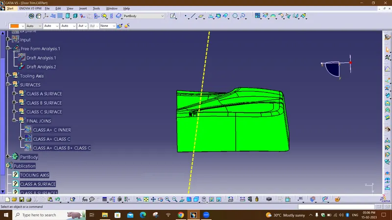
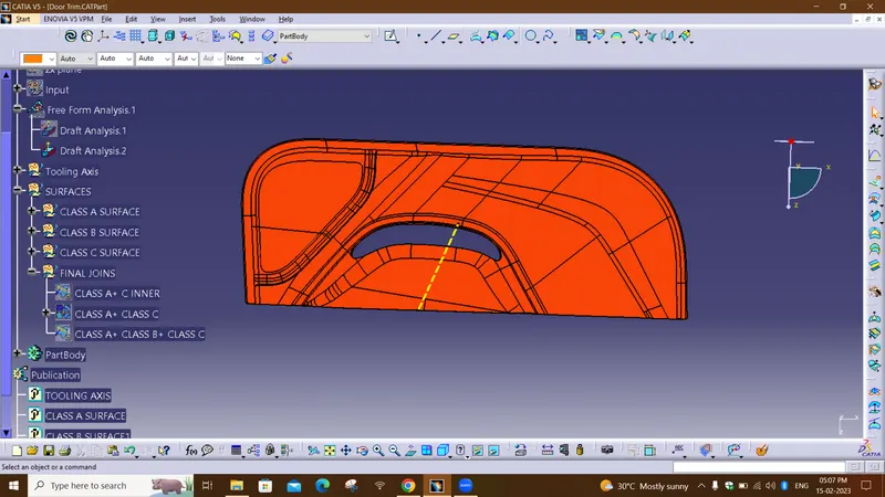
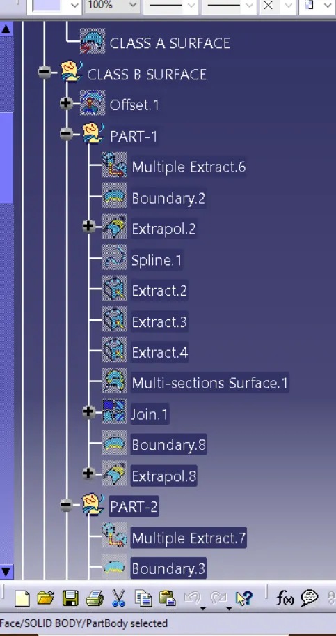
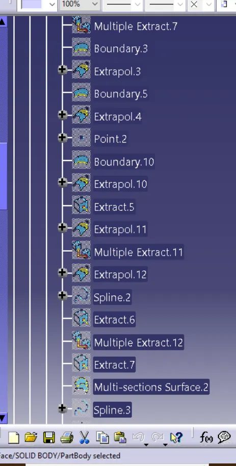
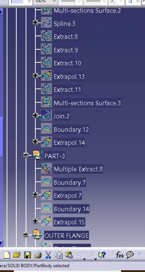
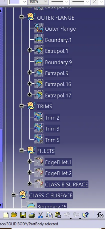
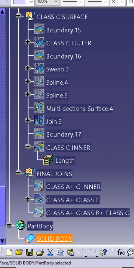
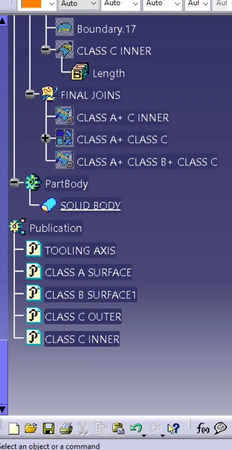
TREE STRUCTURE:
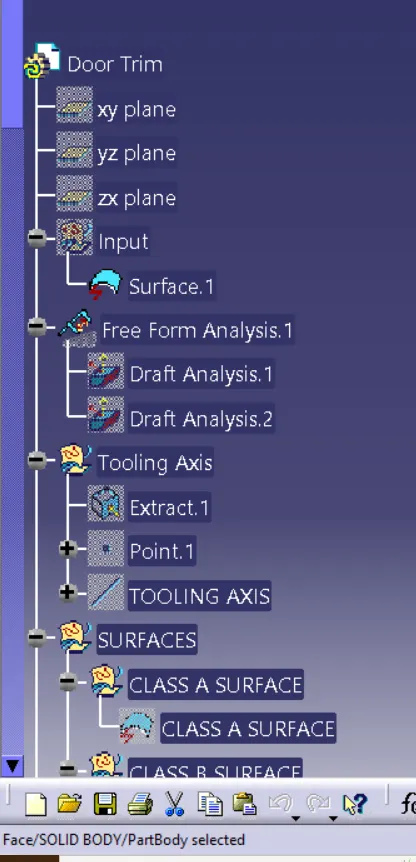
Conclusion
I have successfully created the class-B and Class-C surfaces of DOOR TRIM using the given Class-A surface along with the tooling axis in the CATIA surface workbench.