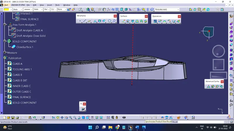
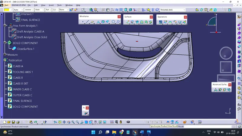
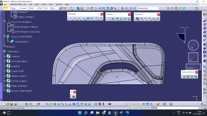
Week 8 - Challenge 5 - Door Trim Lower
Aim:-
Create the Door Trim Plastic component through the given Class-A surface.
Objectives:-
• Creation of Tooling axis with appropriate draft angle.
• Creation of other surfaces (eg, B and C surfaces) for creating a solid component.
• Perform Draft analysis on Class A surface and Solid model hence created.
Abstract:- This report contains a brief theory of creation of door trim soild component from Class A. For creation of solid model need to create a class B& class C and need to run a Draft analysis on component. All procedure of creation of solid component is mension below.
Methodology:
- Tooling Axis
- Draft analysis on class A
- Class B
- Class C
- Joining of class A, class C& class B
- Convert Surface into solid Component
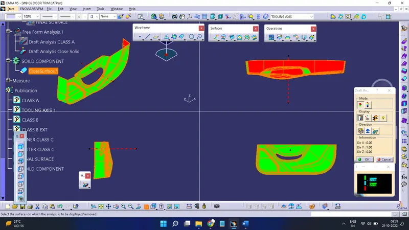
- Draft analysis on Solid Component
- Make Publication
Types Of Surface:
CLASS A:- The Class-A modeling process typically starts with a fully developed design, either as a scanned clay model or an Alias model. Because the design isn't changing, the modeler has the time to build surfaces to the highest quality standards, ready for production. A common method of working is to start with a prototype model and produce smooth mathematical Class A surfaces to describe the product's outer body. From this the production of tools and inspection of finished parts can be carried out. Class A surfacing complements the prototype modelling stage by reducing time and increasing control over design iterations.
Class A surfaces can be defined as any surface, that has styling intent, that is either seen, touched, or both and mathematically meets the definition for Bézier.
CLASS B:- The Class B finish is a quality finish with only minimal imperfections. A Class B finish is the most common finish for exterior surfaces. It is normally specified on surfaces such as external covers, panels, and parts that are fairly prominent. Automotive parts with limited visibility located under the vehicle or under the hood that do not receive a topcoat are typically considered Class B or C, depending on each specific application, OEM and part function or end use.
CLASS C:- surface which is used for joining of class A & class c.
APPROACH:-
TOOLING AXIS:-
A tooling axis is the direction of a component where the component is easily ejected from core and cavity in a particular direction. A tooling axis is a most important for removing material with very finished surface. Before start working and any component it is needed to create a tooling axis firstly
Creation of this axis-
First of all analyse a component for best tooling axis
After analyse extract a one surface from class A.
By use that surface & create a point on it.
Use Line with point-Direction and create a line.
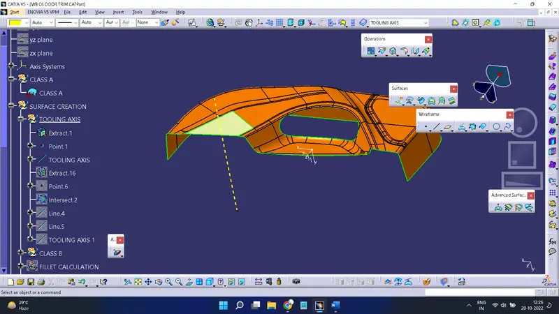
There is other methods also for creation of tooling axis. Eg.- Bisecting line method
Most probably the bisecting method is used for creation of tooling axis
Create a point and add a axis System in a point.
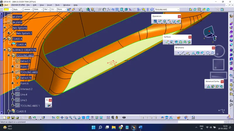
After that create a intersection between a plane and a component
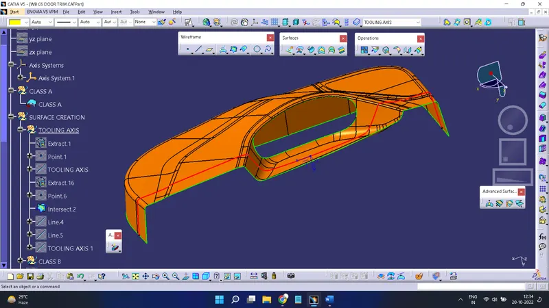
After getting intersection line, create a line which have angle now
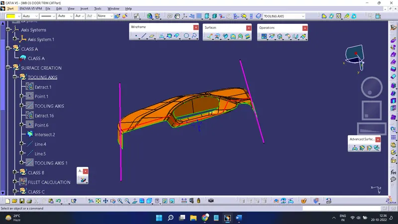
create a line by using a bisecting of two line it will your Y direction
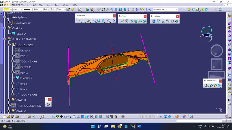
This will be your final tooling access
DRAFT ANALYSIS:-
Attract analysis is helps to detect if the part you drop it will be easily removed in a catia are dropped analysis is performed base on colour rain identify zones
Using a draft and by using a draft analysis we can verify dropped angle examine angle change with a face as well as look at what time line and injection surface in parts
Attract analysis with help to give a proper draft angle at drop triangle describe the amount of paper for mould for a cost part perpendicular to the party line
Minimum draft angle is required 3 degree
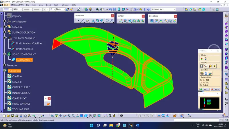
Do a Draft analysis on Class A and see a result.
If every surface is looking good so take this line as Tooling axis.
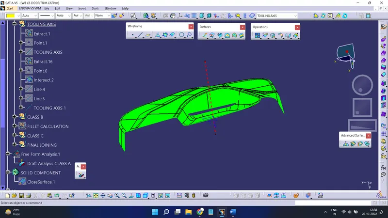
Creation of Class B Surface
For creation of Class B no need to do a same procedure we done before.
For creation of Class B Surface take offset with give thickness of component inside the Class A
The surface which create have some intrups....
So only need to solve by using different tools.
& Create Class B.
Offset Surface
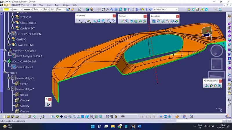
Surface have some intrups...
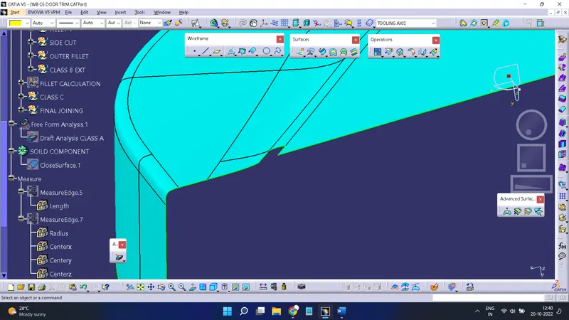
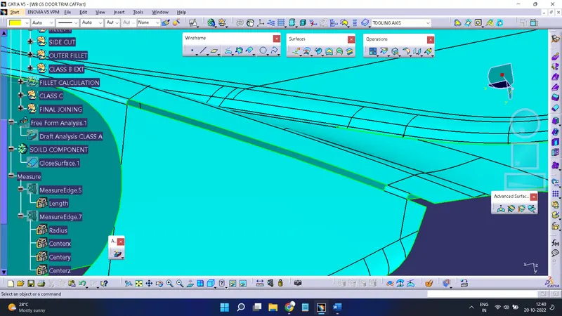
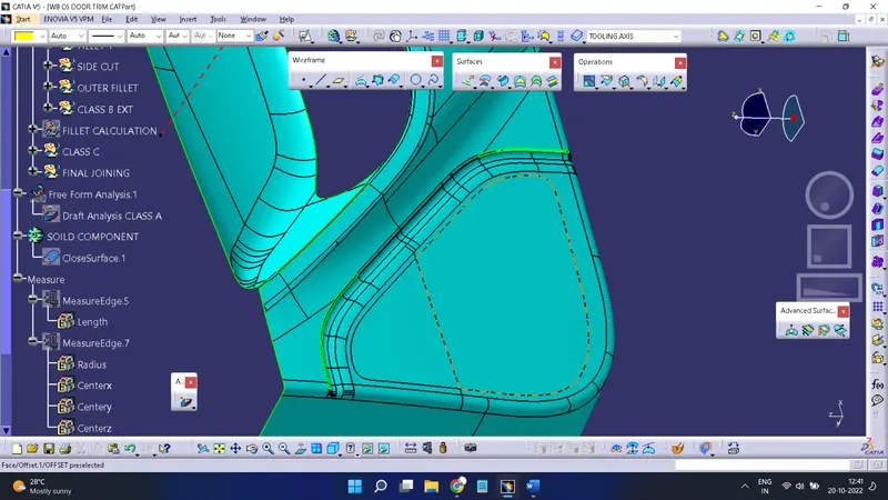
Need to clear all this intrups by using different different tools of GSD
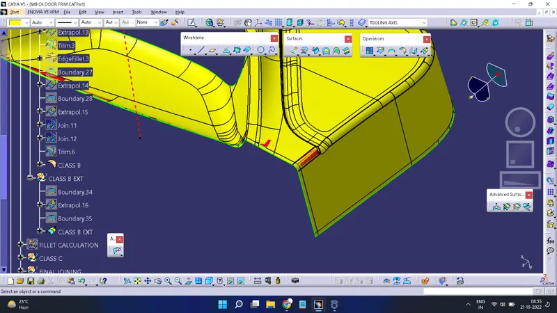
Fixing a fillets first, Take boundary and extrapolate it
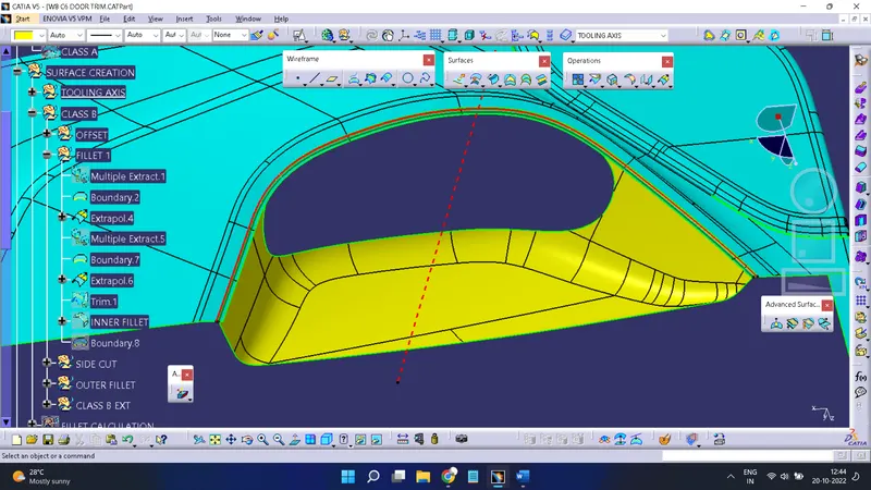
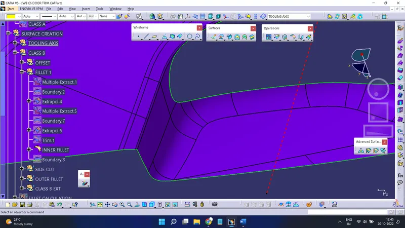
Now Trim both Surface & do fillet
For clear a side cut, Need to create a boundary and use a blend for covering a portion
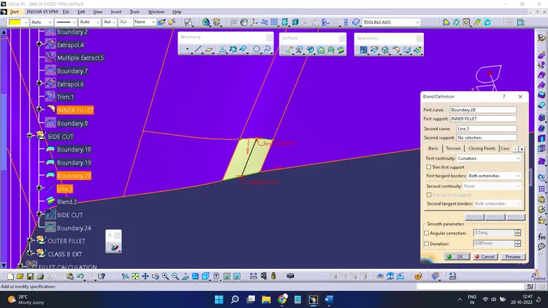
& now join Blend with component
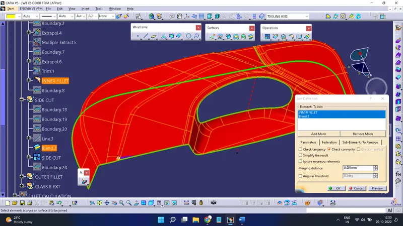
Now need to clear this fillet part
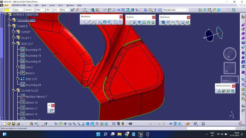
Do Multiple extract& extract parts
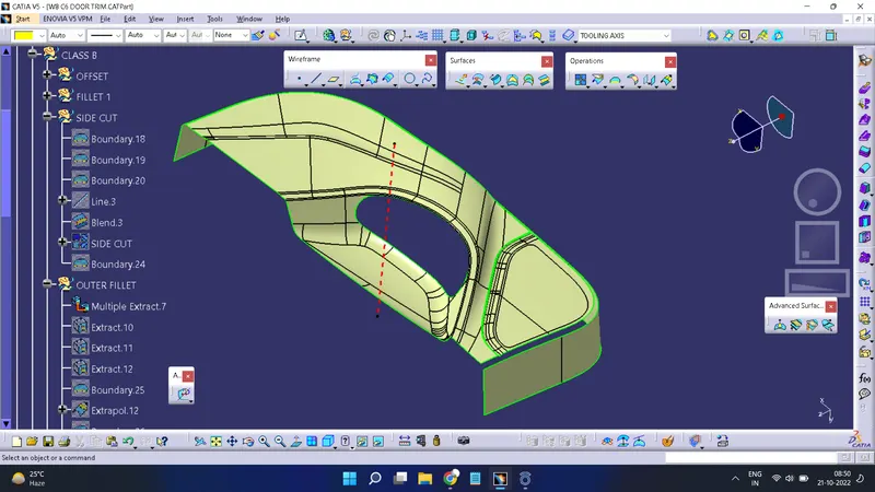
Do Extrapolate, trim then do fillet
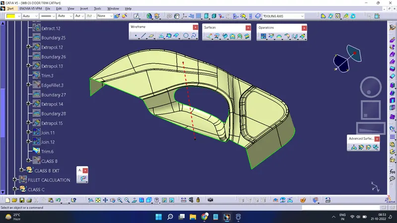
This is Final Class B Surface
After creation of Class B do extrapolate all the outside edge it will help for get intersection easily with class C& Class B.
&This will final Class B Surface.
Creation of Class C surface:
Firstly Analyse the component class C surface.
There is 2 type class C surface can be-
- Parallel to tooling axis
- Perpendicular or with some angle to tooling axis
In this challenge need create class c surface in perpendicular direction with some angle to tooling axis.
Now create a boundary with limits.
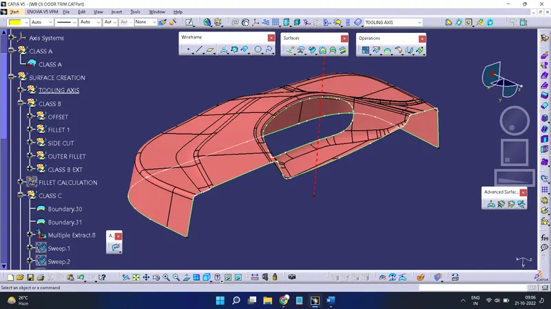
Use a sweep tool for creation of surface
Take limited length with angle 90°-93° .
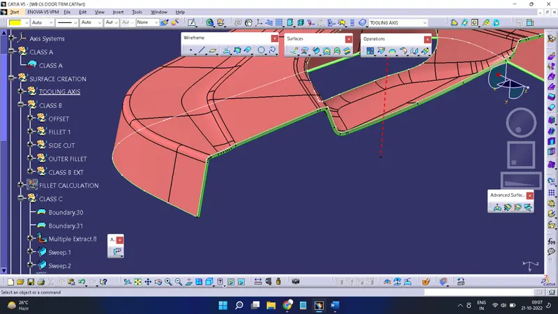
Create all surface for class C and now use a trim to Remove unwanted surface.
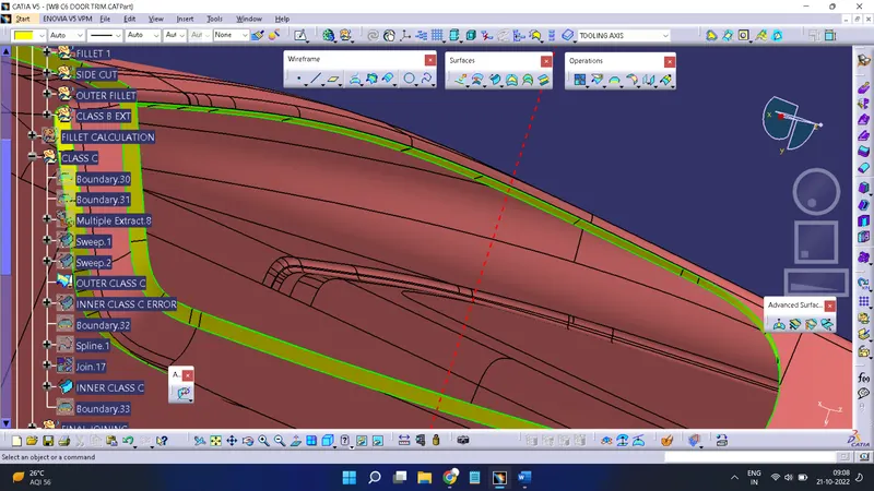
This is Final Class C surface
Final Joining:
Firstly join a class C with class A & get a component
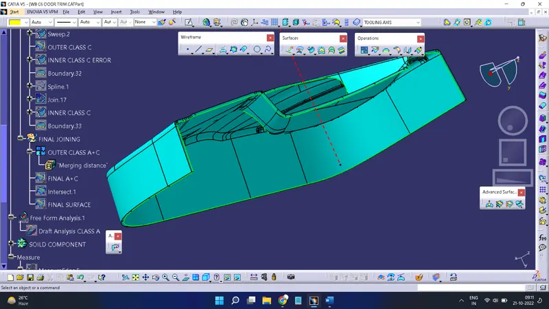
Now Do trim With CLASS A+C & CLASS B
&get a Close surface
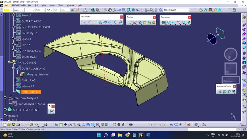
CREATION OF SOLID COMPONENT:-
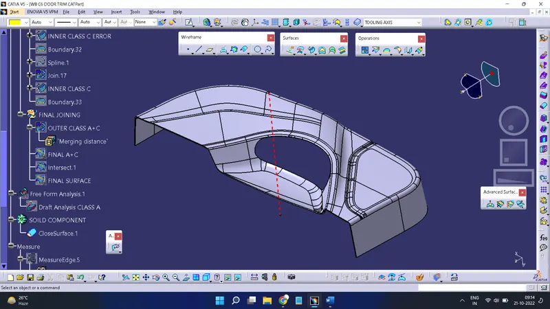
goto Start>Mechenical Design> Part Design
Surface Based Features> Close Surface> Select close surface>OK
& hide surface
DRAFT ANALYSIS:-
A draft analysis is helps to detect a angle of a component. it will be easily removed. In catia a draft analysis is performed based on colour rain identify zones Using a draft and by using a draft analysis we can verify taper angle.
Examine angle change with a face as well as look at what time line and injection surface in parts
A draft analysis help to give a proper draft angle
Draft angle describe the amount of taper of mould which perpendicular to the party line
Minimum draft angle is required 3 degree.
DRAFT ANALYSIS of class A surface:-
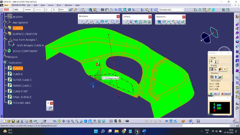
DRAFT ANALYSIS of close surface:-
Different Views of Draft analysis on Solid Model
Creation Of Publication:-
Goto tools> Publication
Select Component which need to Publish then OK.
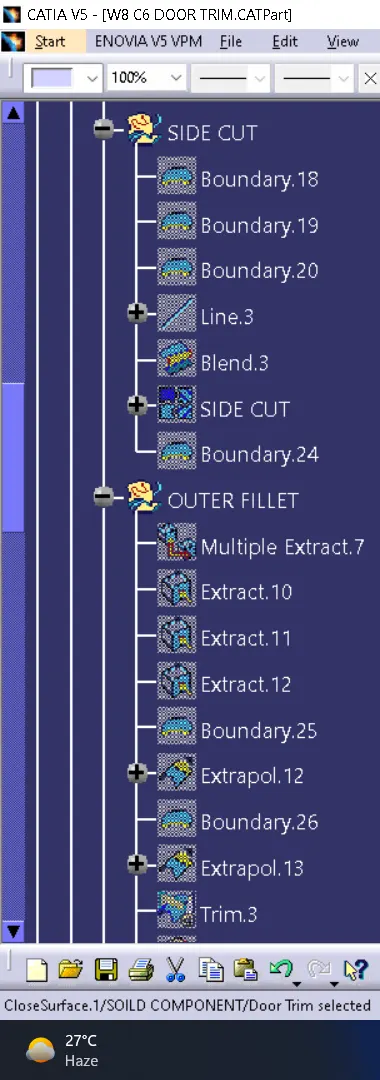
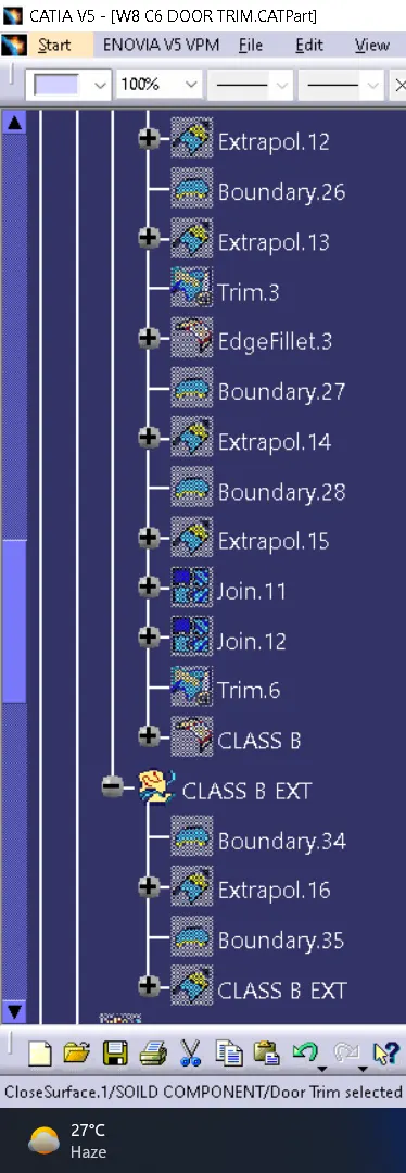
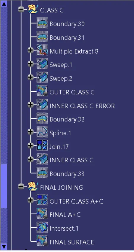
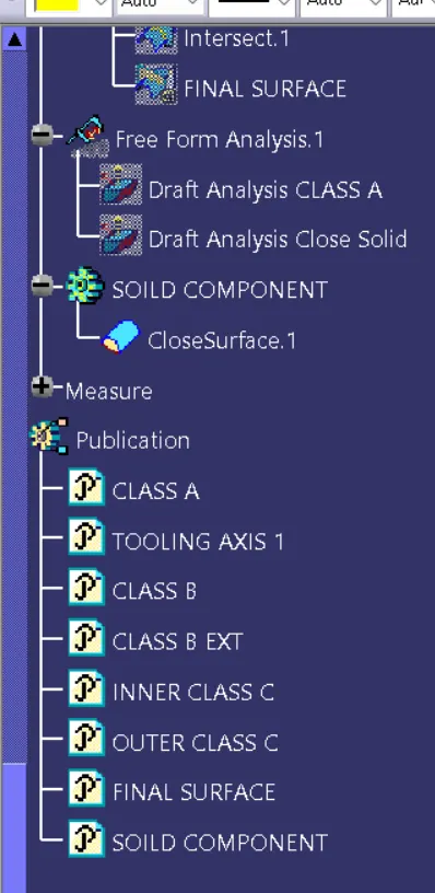
Tree Structure:
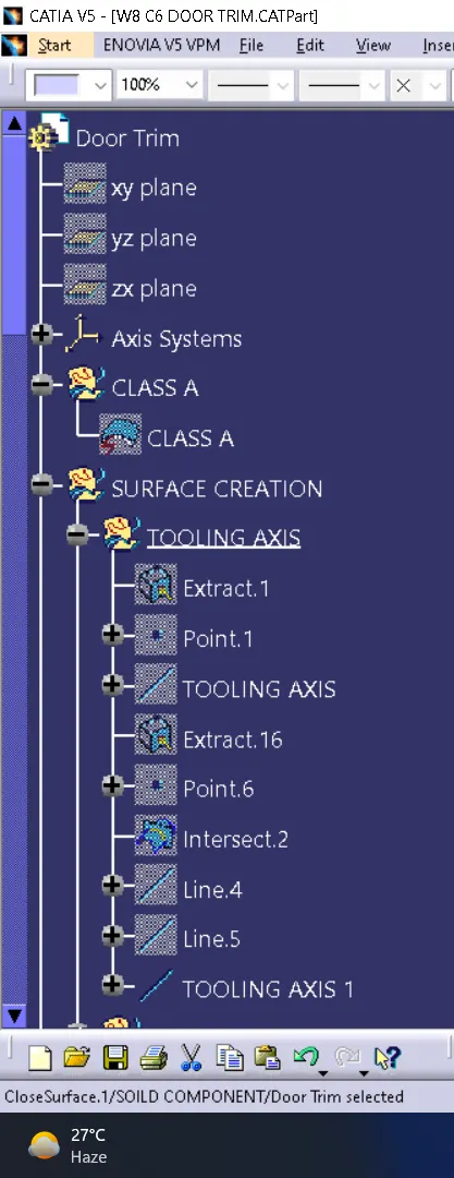
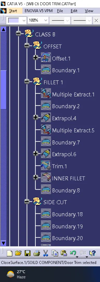
Different Views