Week 8 - Challenge 5 - Core & Cavity Design
AIM:- To create the core and cavity blocks for a switch bezel by considering the all design rules.
Tooling Axis:-
Tooling Direction is basically the direction that the core pulls apart from the cavity. And some components have ribs, pockets, walls.... are going to be drafted based on the Tooling Direction. So make sure the tooling direction which is cover all phases of the components and Core pull apart from the Cavity, nice and clean.
Here using Bisecting method to create a Tooling Axis. There are so many methods to create a Tooling Axis for differnt type of components.
Bisecting Method:-
First check the connectivity of the Class A surface of Switch Bezel model. With help of Join and Boundary commands to ensure that there is a gap between the surfaces.
After that
- First visually check given class A surface for to find out tooling axis which is cover all faces. Herer in this case viewing from Z direction we can clear the face in tooling
- Most of the cases we create the point in holes and pockets of the part, because the holes and pockets is to create a problems when we do the daft ananlysis so we creat a point in mid of the hole. and create a axis system on it.
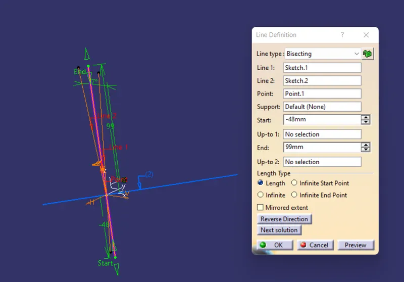
- And using intersect command intersect the surface and draw the lines on the walls and create a disect line with help of b isecting line command. the fallowing window will be appeared .
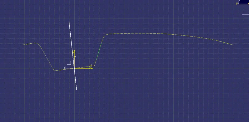
The create the main line. And go to Y direction and do the same process we are done in X direction.
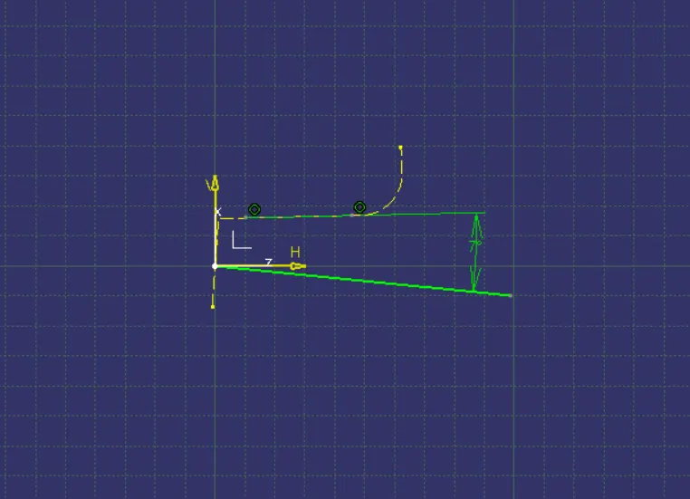
Then bisect these all lines to get the main tooling axis. This toooling axis can be cleared all faces of the part.
DRAFT ANALYSIS:-
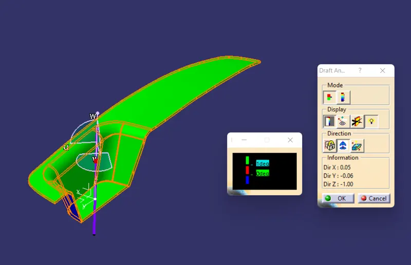
The Draft Analysis command enables you to detect if the part you drafted will be easily removed. This type of analysis is performed based on color ranges identifying zones on the analyzed element where the deviation from the draft direction at any point, corresponds to specified values.
- To perform the darft analysis the view parameters are first set to material mode.
- then go to insert -analysis-feature draft analysis, the following window will be appeared.
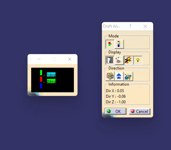
- First select the axis system and drag the axis system to the tooling axis and lock the orientation. This axis system defines the draft direction according to the tooling axis
- Switch on the colour scale and set the draft value 3 degree using colour scale and it will be displayed in green colour any draft angle below 3degree will be shown in red colour.
- Now select the runing point tool to measure the draft angle at the various locations.
CORE AND CAVITY DESIGN for Switch Bezel
Basically the mold is built in two separate pieces, one is Cavity block and other one Core block. The Core pulls apart from the Cavity and that's the Dyeline or the Tooling Direction. Actually core is the depression of the body and cavity si the depressiion of the body. combine this two form a mould. then the plastic material injected into these mould to get a plastic part.
Parting Surface:
injection mold has two major components one is core and another is cavity. during the injection molding process, these two halves are pressed tightly form a sealed hollow to avoid the melt flow leakage and maintain certain holding pressure, the pressed surface are called parting surface, usually parting surface are the biggest projection outline of the part.
Part Line:
It is the area in which parting surface and component meets or it is a junction between core and cavity and the parting surface has some set of rules because the product qulity mostly depends on the parting surface.
DESIGN PARTING SURFACE SHOULD FOLLOW THE FOLLOWING PRINCIPLES:
- Design the injection mold simple as possible. Aviod or reduce side parting as much as possible to reduce cmplexity of the mold marking.
- Easy of demolding as far as possible, for instance the plastic parts should stay in fixed halve of injection mold and should ejected by ejection system avoid, side demolding action.
- Ensure the dimension accuracy of the molded parts, Try to make the parts similar dimension accuarcy reqirements in same mold to reduce manfacturing and assembly errors.
- Ensure apperance reqirement of molded parts, finish or mismatch usually occurs on parting surface, so the parting surface should not be designed on high quality requirement surfaces.
- Ensure adequate venting. if possible parting surface should be palce at the end of the mold flow. This is going to be advantage of filling and venting.
First extrapalted the class A surface
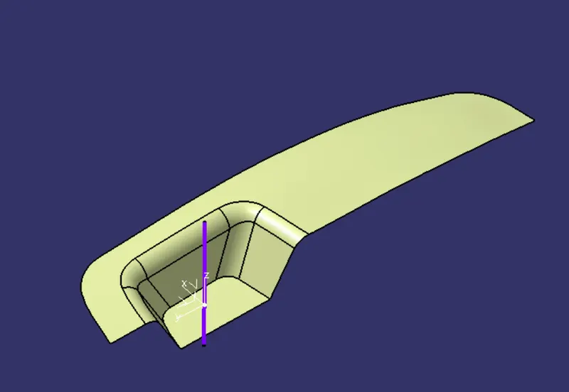
trim extraplate class A surface with class C to get inside portion
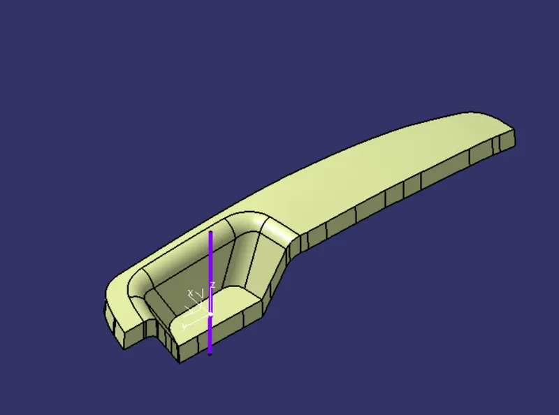 \
\
above trimed surface trime with class B surface to get the prating surface with component area
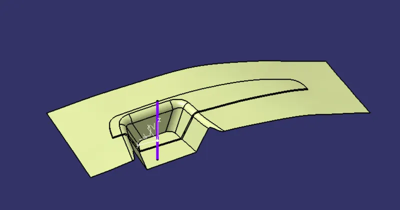
Now, creat a rectangle to cover part surface and extrude it.
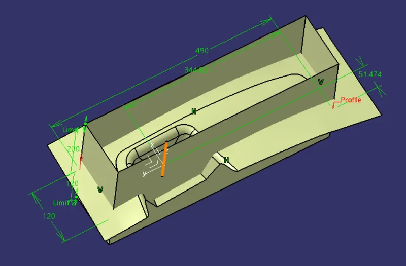
close the core side and trim with parting surface and solid it.
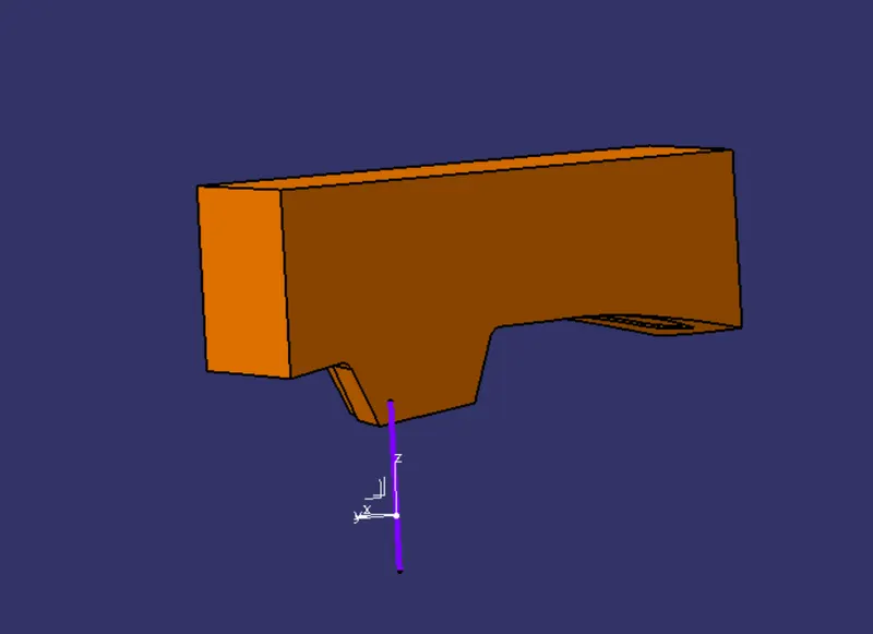
Repeating the same as done for the cavity part and trim it on other side surface
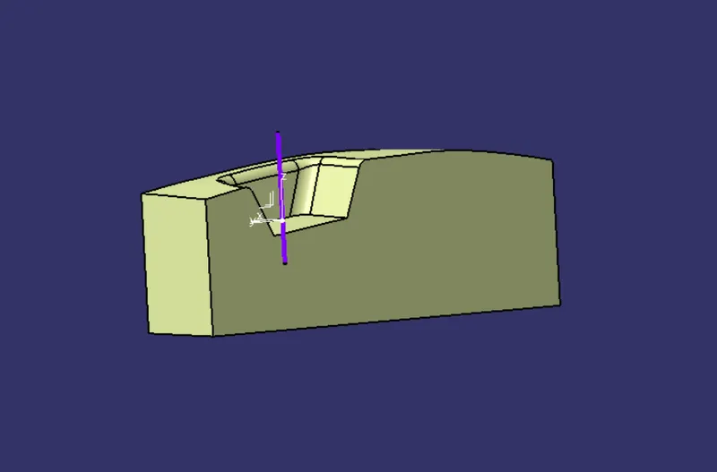
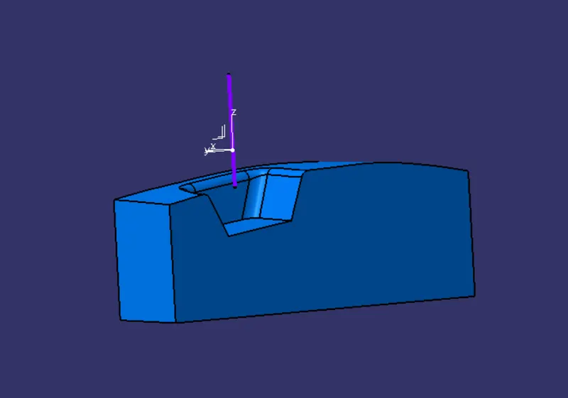
combine core and cavity to form a mold cavity
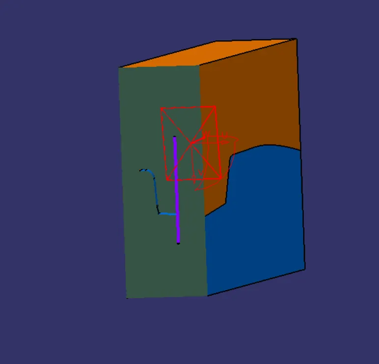
parting surface and parting line
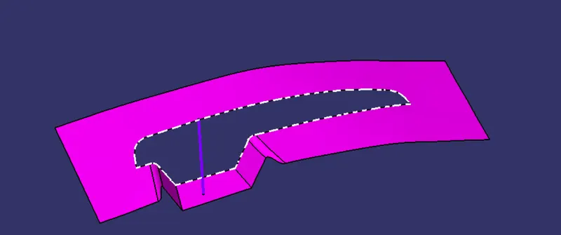
for understanding
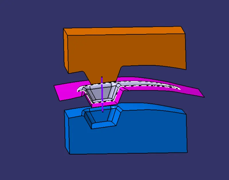
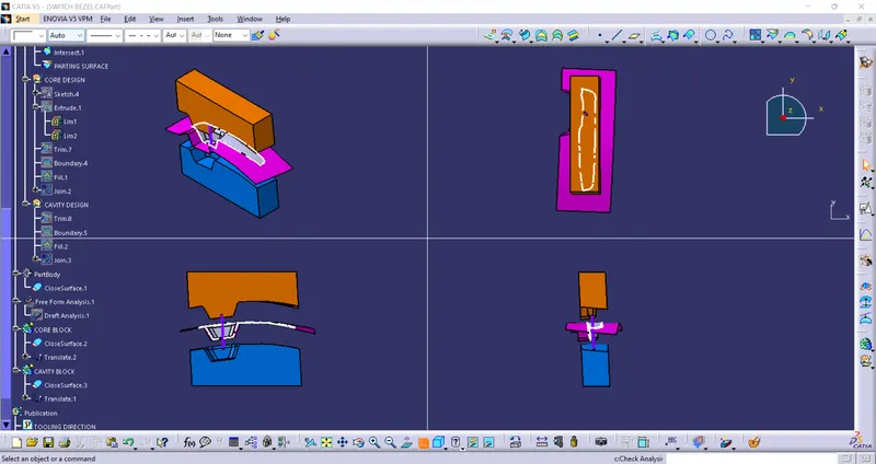
RESULT:-
Core and Cavity blocks for the Switch Bezel have been successfully created.