Week 8 - Challenge 5 - Core & Cavity Design
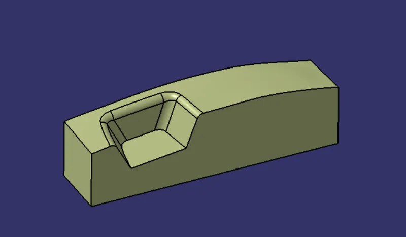
AIM: To create a Switch Bezel component through the given CLASS A Surface and to perform the draft analysis on the component.
OBJECTIVES
- To create the Tooling Axis in the best possible direction.
- Draft Analysis on the CLASS A Surface and the Final Plastic Component.
- Creation of CLASS B and CLASS C Surface.
CLASS A Surface
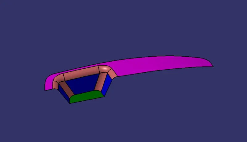
PROCEDURE FOR DRAFT ANALYSIS
- First check the connectivity of the given CLASS A Surface by using the Join or the Boundary command to ensure there is no gap in between.
- Analyze the best possible tooling axis for the given component.
- Proceed with the TOOLING AXIS with the New Axis System.
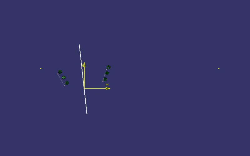
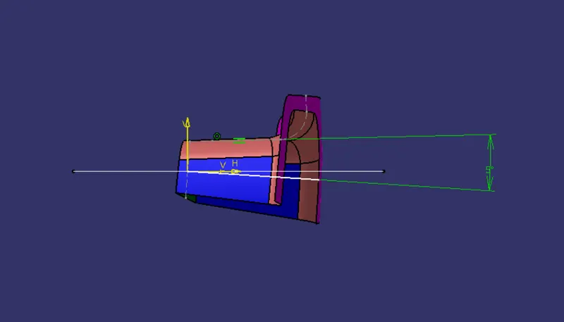
Bisecting Line: The bisecting line is the line splitting in two equal parts the angle between these two lines.
Main Tooling Axis
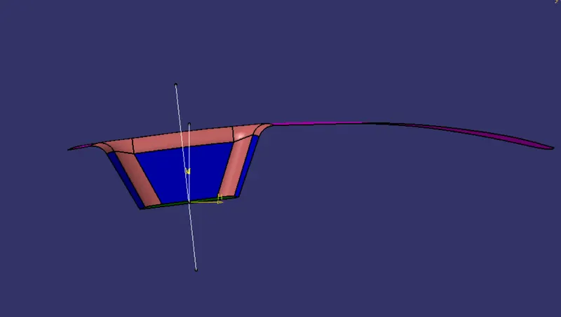
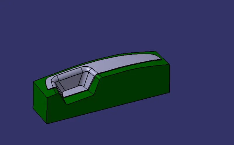
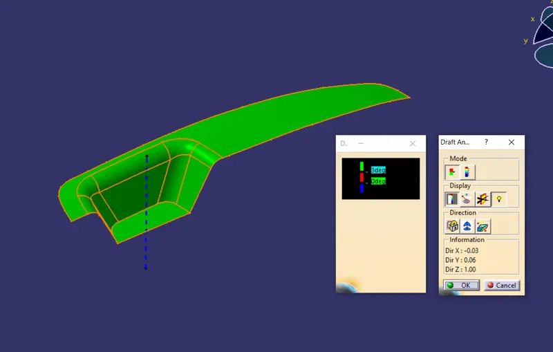
Draft Analysis On CLASS A Surface
- Select the Material Mode in the Toolbar for Draft Analysis
- Add the Compass to the main Tooling axis and lock the tooling position.
- Click on the Surface for the output of the analysis.
CREATION OF B SURFACE
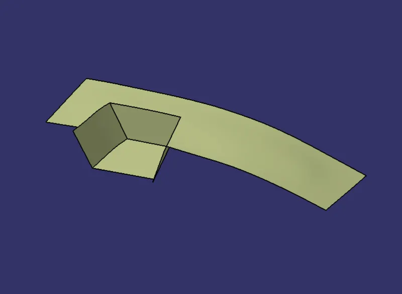
- First extract the surface from the given CLASS A Surface and untrimmed them to obtain the Parent Surface
- After untriming , all the surfaces are then extrapolated.
- Offset the untrimmed surfaces to the required thickness i.e 2.5mm
- At last trim the offset surfaces to obtain the required final trim.
CREATION OF CLASS C
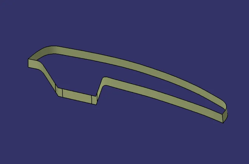
- For creating a CLASS C surface we extracted the boundaries of the CLASS A using Multiple Extract.
- These extracted boundaries are now swept along the Main Tooling Axis with 3 deg draft.
CLASS A +CLASS C
To ensure there is no gap between the CLASS A and CLASS C surface we have joined the two surfaces.
FINAL TRIMS
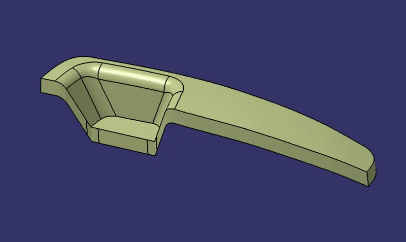
The joined CLASS C surface is now trimmed with the CLASS B Surface to obtain the final trim.
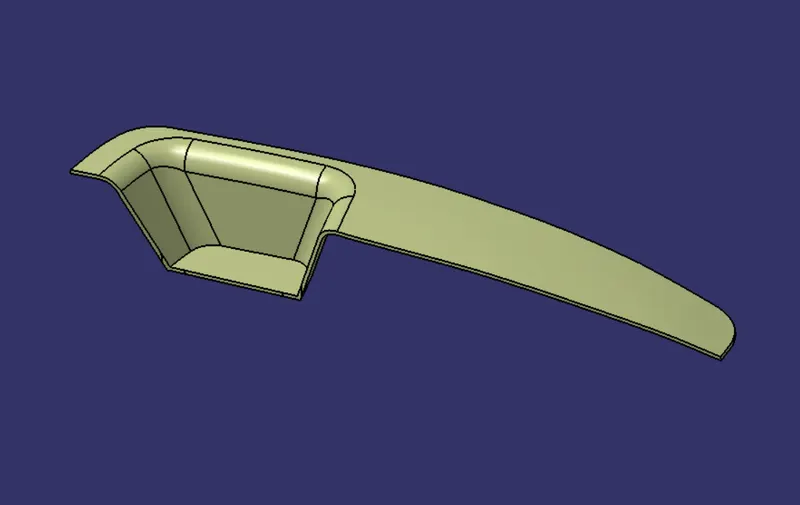
CLOSED SURFACE
The final trim is now closed using the closed surface command in the part workbench to obtain the final solid component.
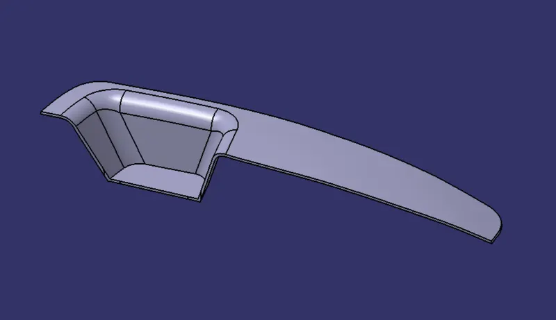
DRAFT ANALYSIS ON THE FINAL COMPONENT
The following results were obtained in draft analysis of the final component.
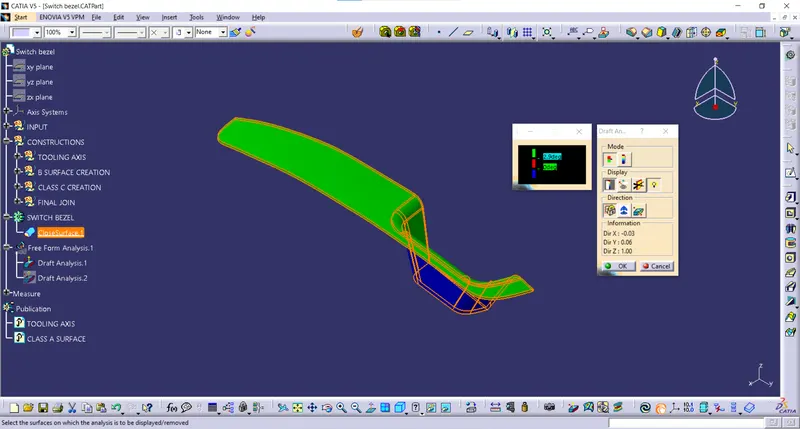
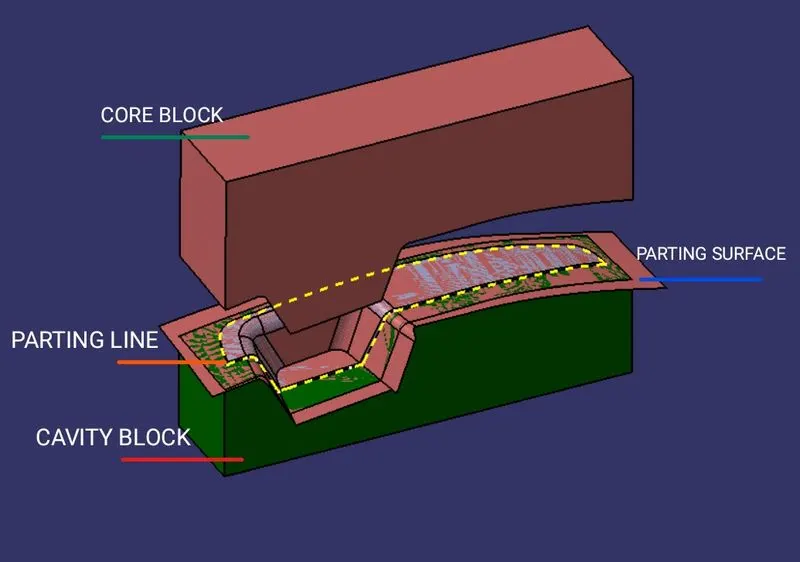
CORE AND CAVITY DESIGN
CORE AND CAVITY:In a typical injection molding machine, one half of the mold (the A-side) is attached to the fixed side of the press, and the other half of the mold (the B-side) is attached to the moving clamp side of the press. The clamp (or B) side contains the ejection actuator, which controls the ejector pins. The clamp forces the A and B-sides together, molten plastic is injected into the mold and allowed to cool, the clamp pulls the B-side of the mold away, the ejection pins are actuated, and the part releases from the mold.
PARTING SURFACE
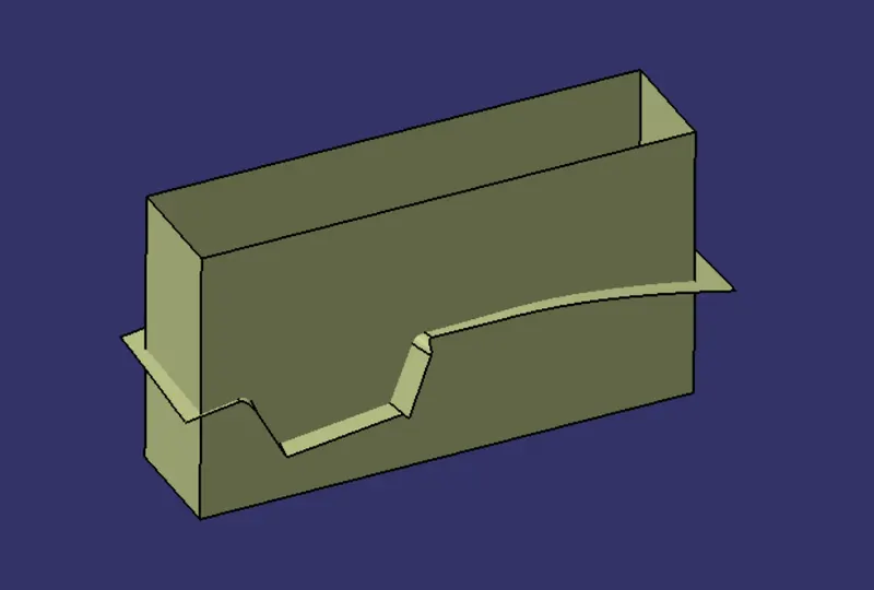
A parting surface is a surface that separates the mold block into two parts – the core and the cavity.
PARTING LINE
When referring to injection molded parts, the phrase “parting line” refers to a line on the part that is created where the two halves of the mold come together.
DESIGN PARTING SURFACE SHOULD FOLLOW THE FOLLOWING PRINCIPLE:
- Design the injection mold structure as simple as possible.Avoid or reduce side parting as much as possible to reduce the complexity of mold making.
- Ease of De-Molding , as far as possible the plastic part should stay in a fixed halve of the injection mold and should be ejected by the ejection system ,a void side de-molding action.
- Ensure the dimensional accuracy of the molded parts.Try to make the parts with similar dimensional accuracy requirements in the same module to reduce manufacturing and assembly errors.
- Ensure appearance requirement of the molded parts.Flash or mismatched occurs usually on parting surface, so the parting surface should not be designed on CLASS A Surfaces.
- Ensure adequate venting.If possible , parting surface should be placed at the end of the mold flow. THis is going to be a good advantage of filling and venting.
MAKING THE CORE BLOCK:
- Extrapolate the CLASS A Surface by creating a boundary of the CLASS A Surface.
- Trim the Extrapolated CLASS A Surface with CLASS C Surface created.
- Trim the above with the CLASS B Surface , to get the CORE Part.
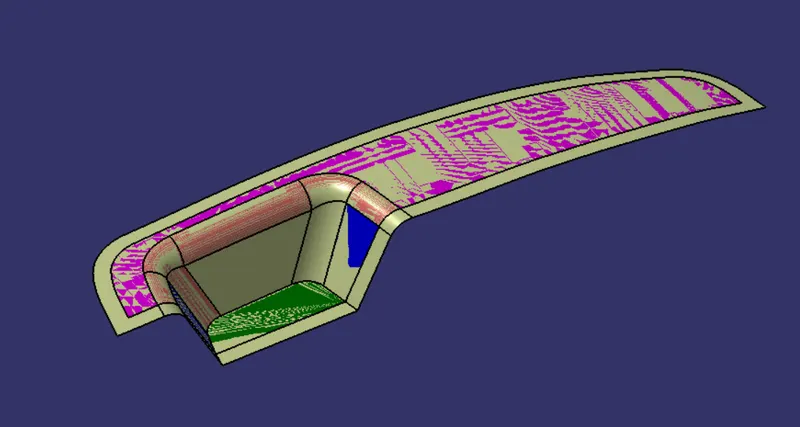
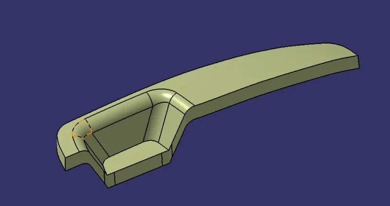
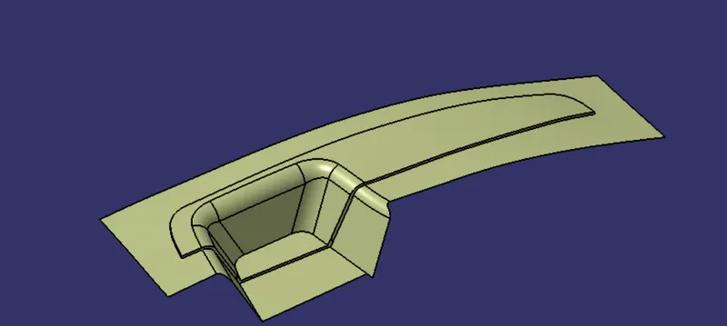
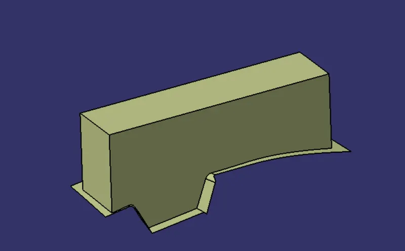
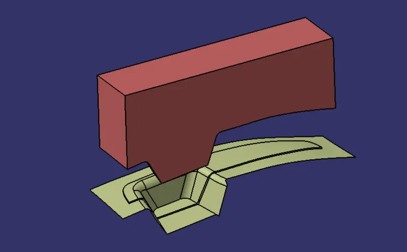
Proceed with the making of CORE BLOCK
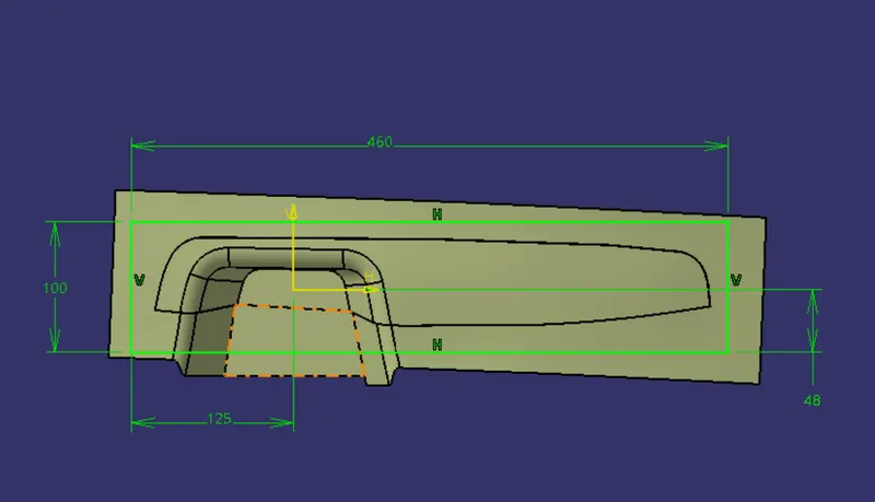
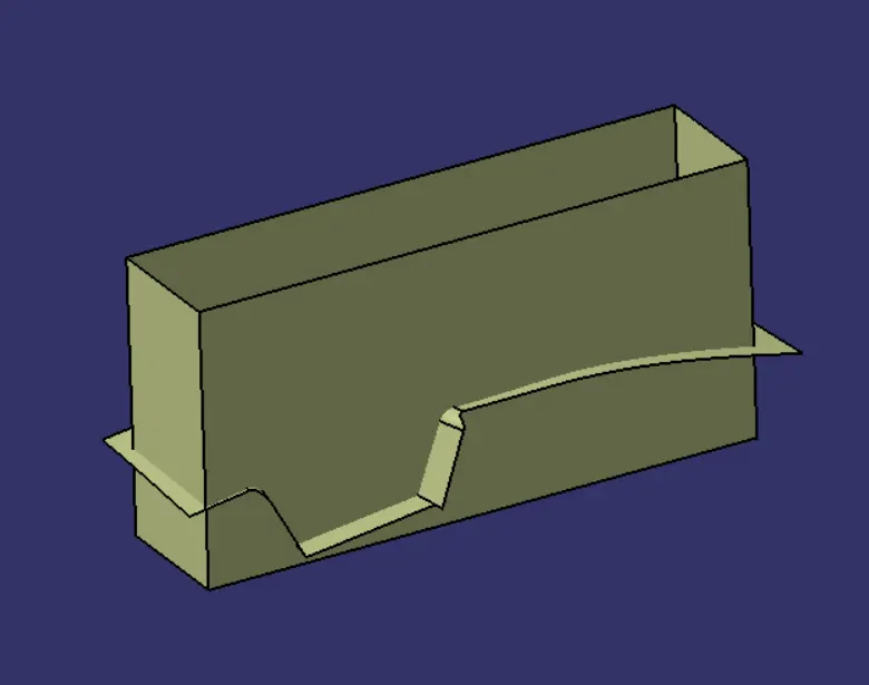
Extrude the sketch created with the Tooling direction on the Parting Surface for making the core block.
CAVITY BLOCK
Follow the similar kind of steps as in the CORE block , for making the cavity block.