Week 8 - Challenge 5 - Core & Cavity Design
DRAFT ANALYSIS
Objective :
The main objective is to create a tooling axis for a given Switch bezel by satisfying the construction of surfaces and to perform draft analysis to check if the part has given draft to the surfaces which are lying parallel to the tooling axis.
DRAFT -
In engineering, draft is the amount of taper given to the surface of moulded or cast parts perpendicular to the parting line. The in build draft analysis tool used in CATIA to ensure that the faces are taper with the respect to the tooling axis. The tooling axis is the direction of mould part ejection. The draft is provided on both core and cavity sides of the parts, which are produced using moulding, to reduce damage to the surfaces during ejection. Usually the draft angle should be 3 degrees.
Procedure :
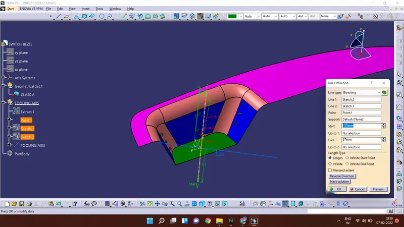
The tooling axis is created by taking reference of the taper surfaces of the given CLASS A surface of the switch bezel. Both the tapered faces of the given surface are extended from the intersection lines, and then both intersection lines are bisected.
After the creation of the tooling axis, draft analysis is carried out with reference to the tooling axis.
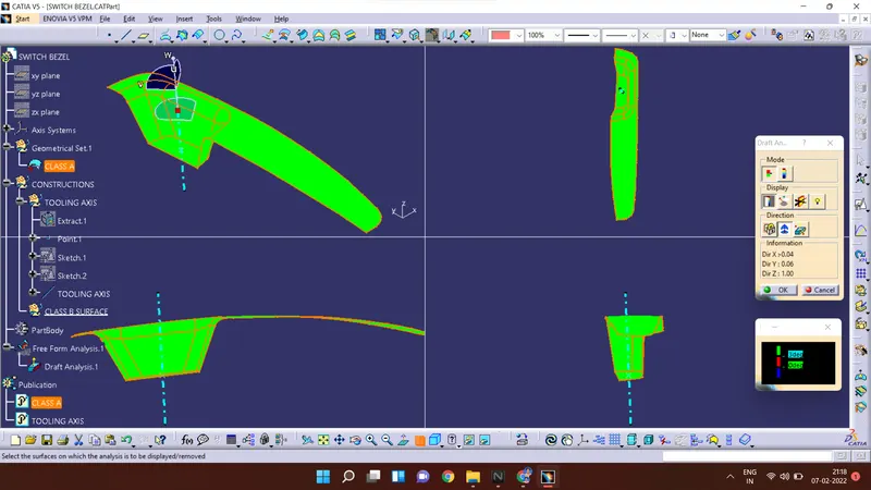
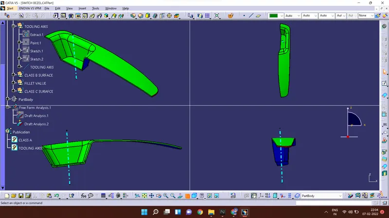
The draft analysis is carried out on the given CLASS A surface, it observed that, all the surface are having green colour which indicates that the surfaces are provided with the minimum draft angle.
CLASS B SURFACE
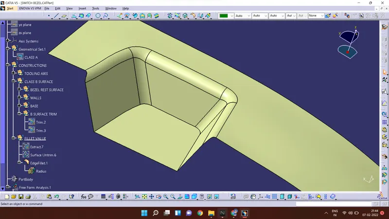
The CLASS B surface is created with reference to the given CLASS A surface using the various features such as, extract surfaces, untrim, extrapolate, offset surfaces. All the created surfaces are trimmed properly and they are joined together.
CLASS C SURFACE
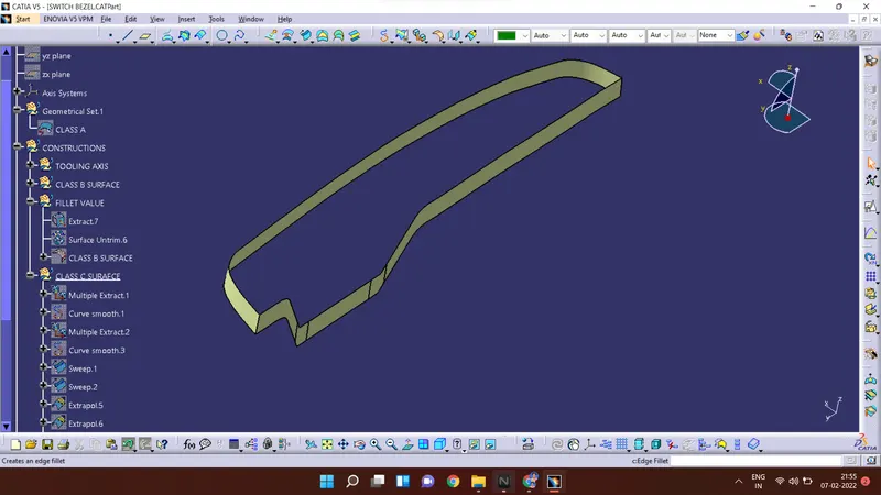
By taking the boundary of the CLASS A surface, a CLASS C surface is created. The extracted boundary is swept with the draft direction
DRAFT ANALYSIS
The draft analysis on final plastic part
CORE AND CAVITY DESIGN
Objective :
To create the core and cavity to the given switch bezel by considering the design rules.
CORE & CAVITY - The core and cavity are the two parts of the mould, in which one is movable, and another one is fixed. In most of the cases, the cavity is fixed to the machine bed and the core is movable with the help of hydraulic and pneumatic.
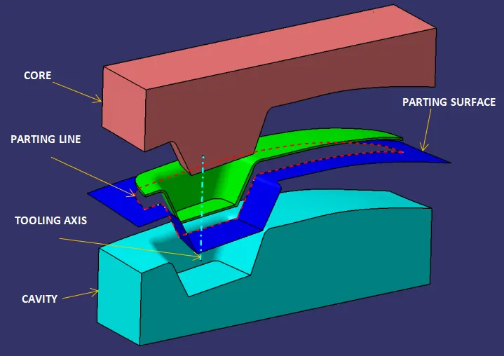
As shown in the above image, the cavity shapes the outer side of the part and core extracts the inner shapes of the plastic parts. During plastic injection, the core and cavity are firmly held together to create the cavity to the part produced.
The main steps involved in designing of core and cavity include the design of parting surface and parting line also. Initially, the parting surface is extracted from the previously generated the CLASS B and CLASS C surfaces. Later, core and cavity are created. Finally, a parting line is generated from the core and cavity.
Procedure :
PARTING SURFACE -
The rule that we have to follow here is, always create the parting surface on B surface side, because, At the parting lines, a plastic defect is caused during injection process namely flash which may disturb the quality of the CLASS A surface if parting surface is on A side. We always create the parting surface on CLASS B surface side.
Parting surface design directly affects the product quality, ease of construction and operation of the injection mould. The mould design is the one of the key factor to the success of the product produced.
The main design considerations that has been followed during design of the parting surface are, the mould is as simple as possible, it will accommodate ease of de-moulding, ensure the dimensional accuracy of the part, the surface should not be designed on any high quality requirement surfaces and moulds are designed with adequate venting.
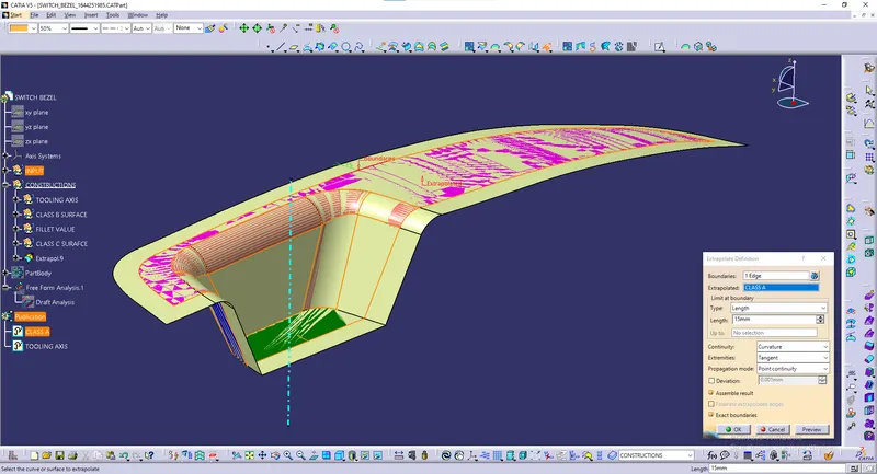
Extrapolate the CLASS A surface for the length of 15 mm as shown in the below picture.
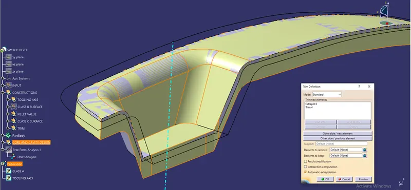
Trim the extrapolated of CLASS A surface with CLASS C surface
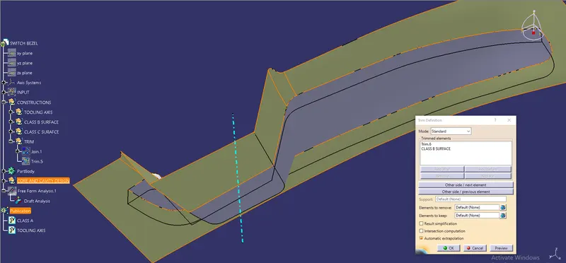
Now trim this with CLASS B surface as shown
Now a part shaped cavity is designed on the core side as shown in the below picture
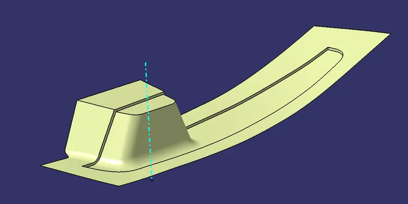
CORE DESIGN -
Insert an axis system and create a positioned sketch as shown
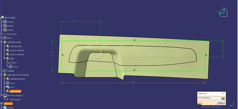
Extract the surface from profile as shown
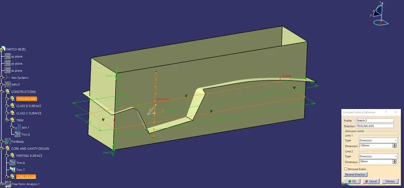
Trim the both surfaces as shown
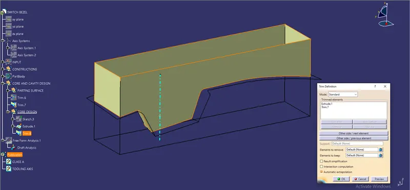
Fill top side of the core using fill surface feature
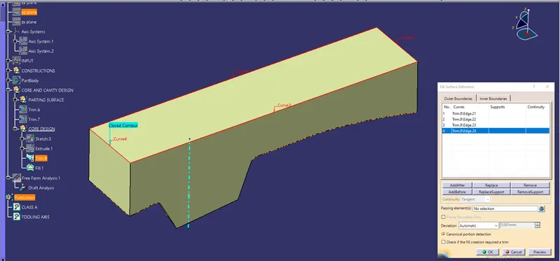
CAVITY DESIGN -
Unhide the extruded surface and the CLASS B surface
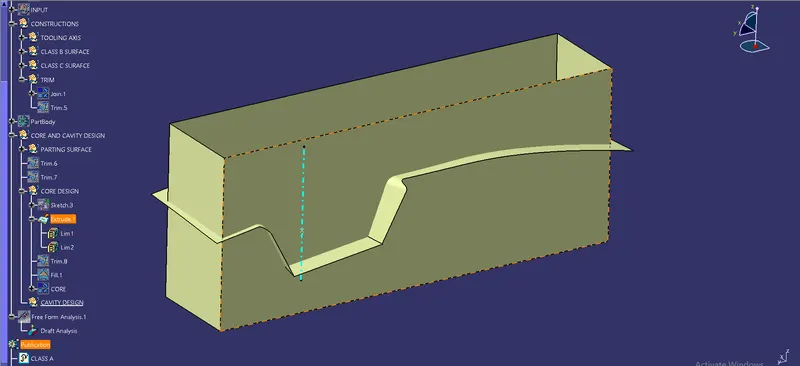
Trim both as shown
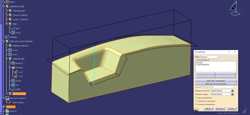
Cavity is created by joining both fill and trim
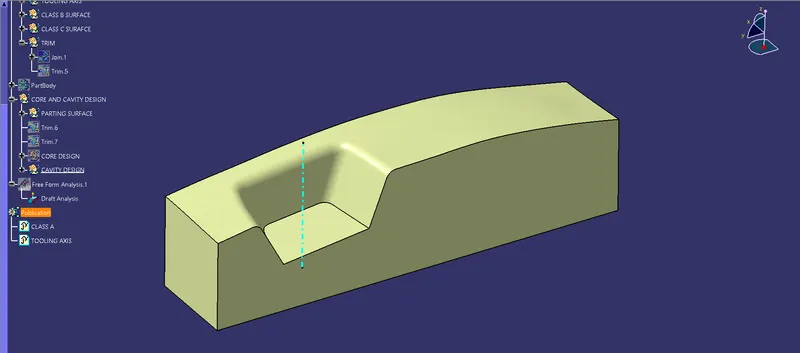
The below picture shows the cross-section of the core and cavity
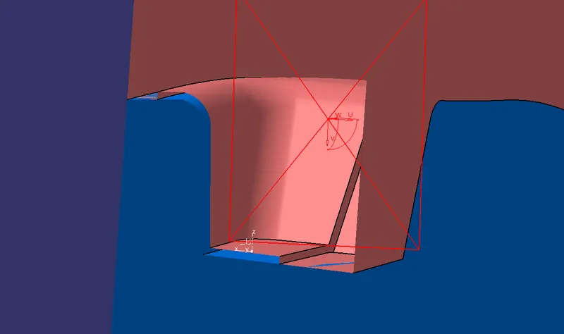
PARTING LINE AND PARTING SURFACE -
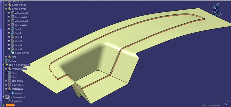
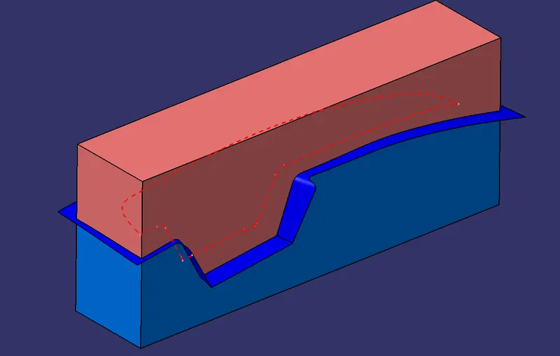
Parting line is a line which intersects the part on the parting surface. It means it is the intersection of both the CLASS B and CLASS C surfaces.
Unhide the CLASS B and CLASS C surface
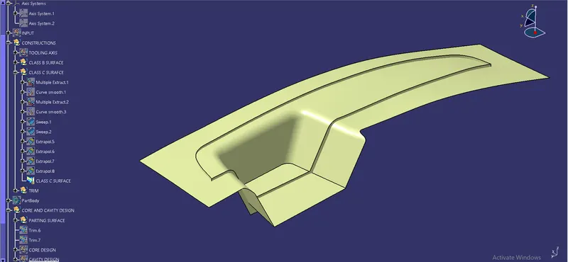
From the below figure, the red dotted line indicates the parting line which is the intersection of CLASS B and CLASS C surface
Split the parting line with CLASS B surface which will create the actual parting surface
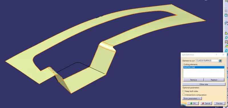
The below picture shows the parting surface, parting line, core and cavity.
The below picture shows the all the elements in the core and cavity design
Tree structure :
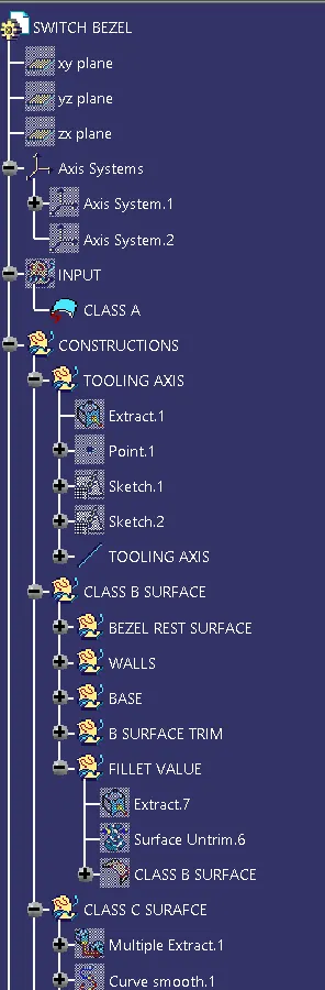
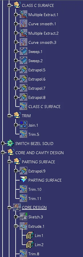
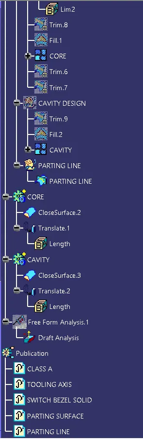
Conclusion :
The tooling axis for the given CLASS A surface of switch bezel is created. The draft analysis is carried out on the CLASS A surface with respect to the tooling axis.
The Core and Cavity are designed with reference to CLASS B and CLASS C surfaces. Parting line and parting surface are generated and the majojn elements are published.
Thank You