Week 8 - Challenge 5 - Core & Cavity Design
HELLO SIR,
Week 8 - Challenge 5 - Core & Cavity Design
OBJECTIVE:-
- Create the Core and cavity blocks for the switch bezel
- A detailed report should be done explaining the draft analysis and the tooling axis creation.
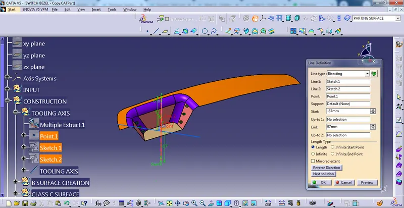
- An explanation should be given on the way of creating the tooling axis, particularly the Bisecting method.
CREATION OF TOOLING AXIS:-
Using Bisecting Method
First of all, click the multiple Extract command to extract the base of the CLASS A surface, then create a point using the point command, and then create an axis system into the point.
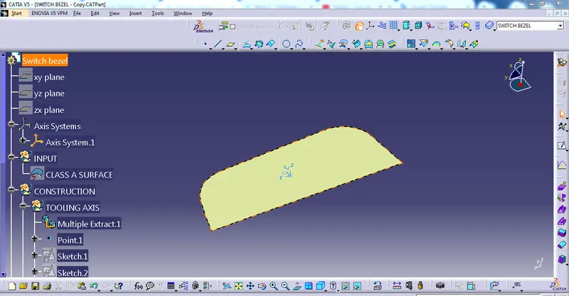
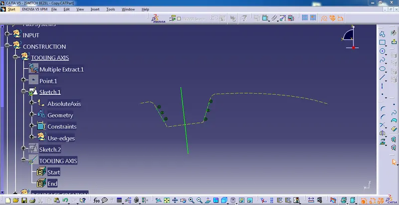
After that, create a sketch 1 on the y-z plane then bisect the two-line.
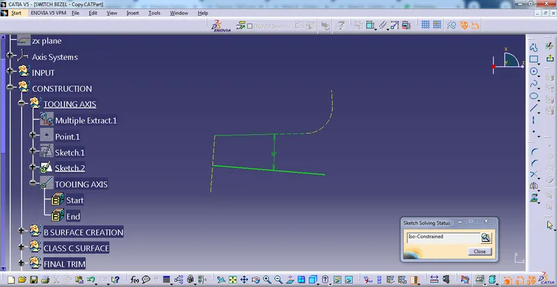
Again, create a sketch 2 on the z-x plane then bisect the two-line.
After bisecting Sketch 1 and Sketch 2 we get a Tooling Axis
DRAFT ANALYSIS OF SWITCH BEZEL
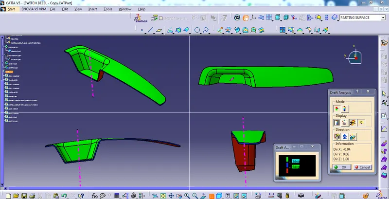
First, we have to customize the view parameter, I select the materials option, and go to the draft analysis command it will appear on the screen then select the compass and then drag and drop the tooling axis. then click the model and see the report of draft analysis.
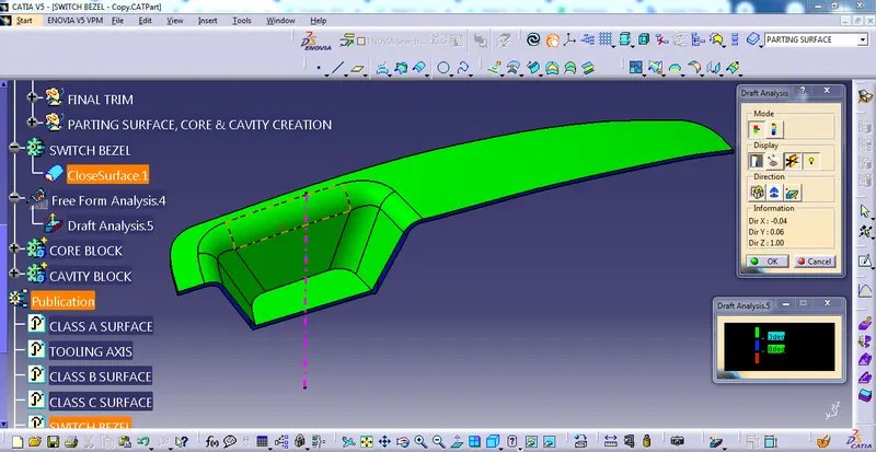
FRONT VIEW, SIDE VIEW, TOP VIEW, AND ISOMETRIC VIEW
CREATION OF PARTING SURFACE, CORE BLOCK & CAVITY BLOCK
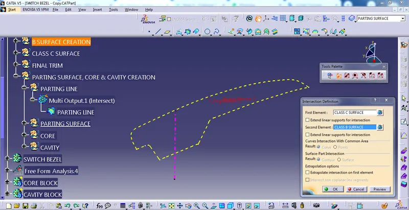
PARTING LINE:-
A parting line is a separation on the plastic part where the two halves of the plastic injection mold meet
for the parting line, I created the intersection between class B ad c surfaces.
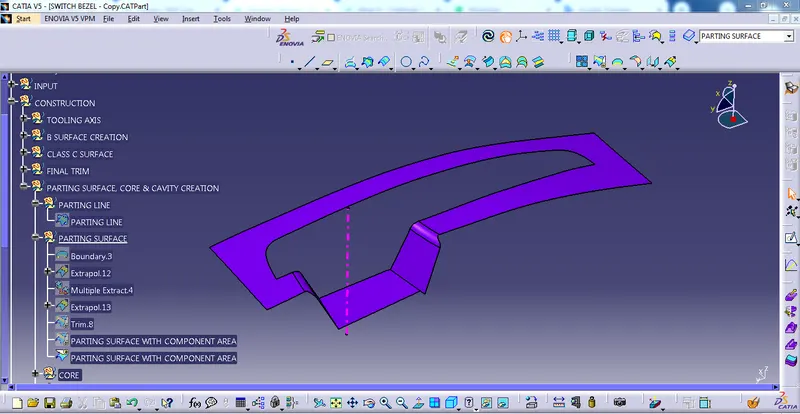
PARTING SURFACE:-
the parting surface is the point where the core and cavity meet together and in this case, our class B surface can be a parting surface because core and cavity have been created with class b surface so in this case, I split the class b surface with my parting line so, now we have got parting surface
with the component area
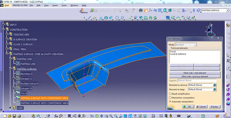
without the component area
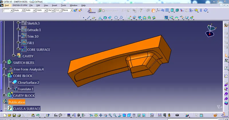
CORE SURFACE & CORE BLOCK
I drew a sketch then extrude the surface then go to the trim command to trim the unwanted surface. then go to fill command to fill the surface then, we have got a core surface.
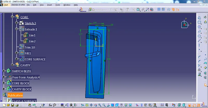
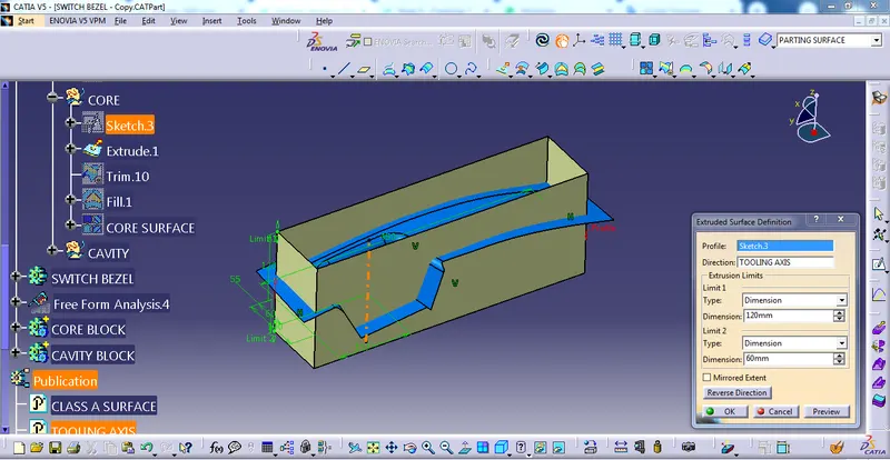
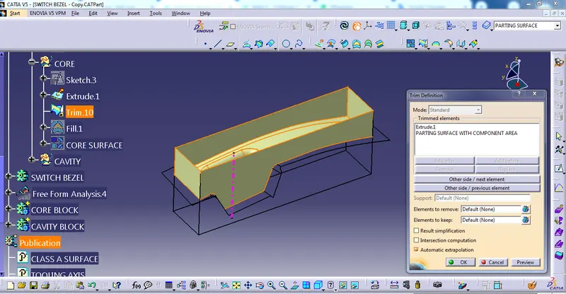
CORE SURFACE
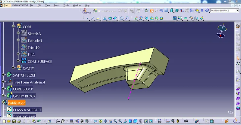
now I have got a complete close surface then we have to be ready to solidify then we have got CORE BLOCK
CAVITY SURFACE & CAVITY BLOCK
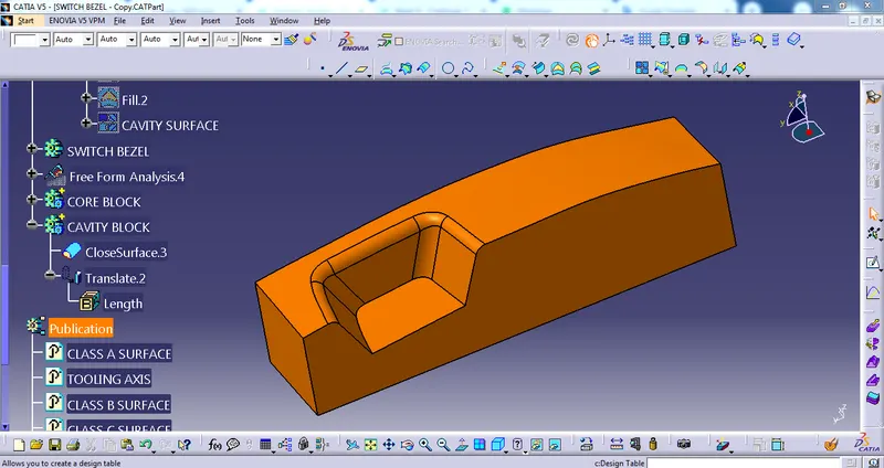
Using the same procedure to i make cavity surface and cavity block
CAVITY SURFACE
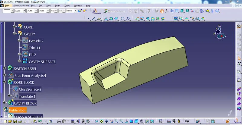
CAVITY BLOCK
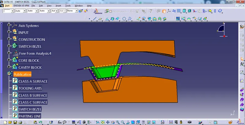
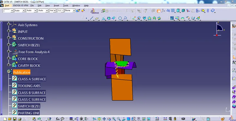
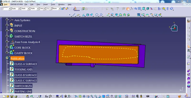
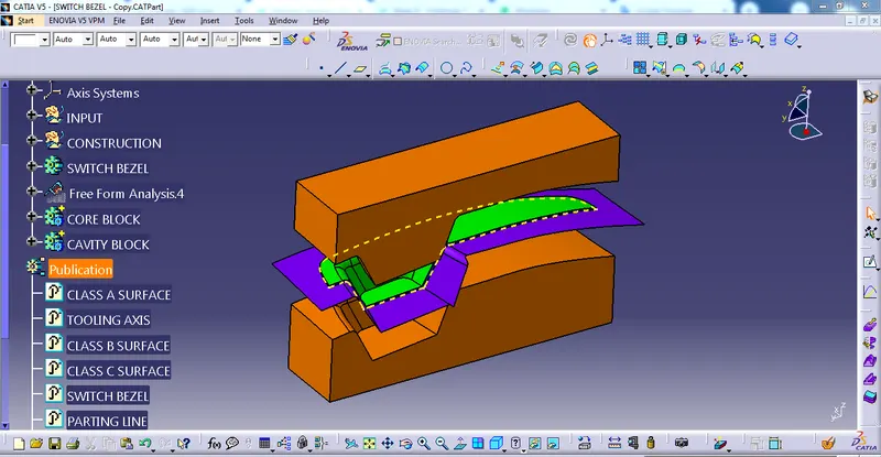
FRONT VIEW, SIDE VIEW, TOP VIEW AND ISOMETRIC VIEW OF CORE & CAVITY
CONCLUSION:-
Confirming the appropriate draft angle required for the component to be manufacturing is one of the important aspects before continuing the design further.
Add a minimum draft of the part to release from the mold. because it prevents damage from happening to the component while coming out of the mold.
THANKS