Week 8 - Challenge 5 - Core & Cavity Design
DESIGN OF CORE AND CAVITY
The core and cavity design is necessary in order to manufacture the designed component. The core is the projection of the component and the cavity is the hollow space having the component like structure. The point/surface at which the core and the cavity meets is called as the parting surface. The parting surface is always present at the B side of the component. Here the main task is to design the core and cavity.
The core and cavity of switch bezel is to be designed.
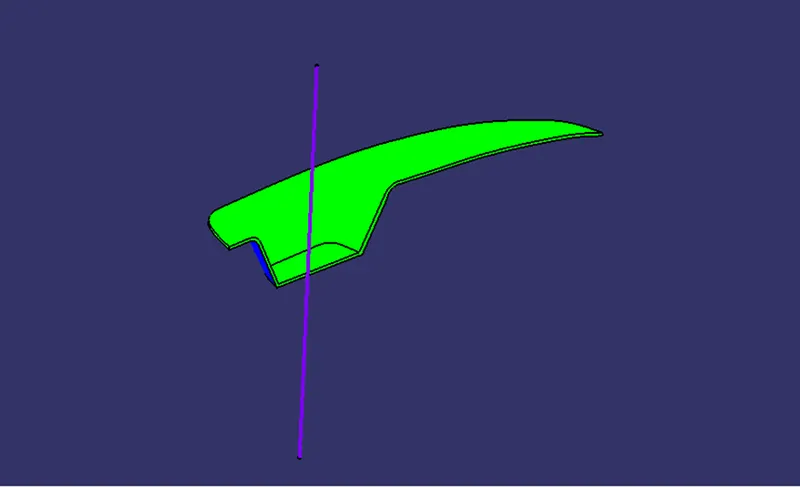
Initially the design of the parting surface is created and then the core and cavity is designed.
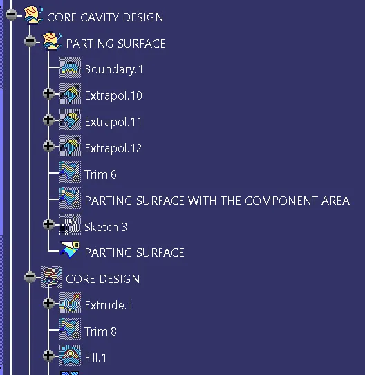
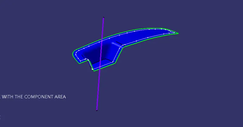
Now to create the parting surface initially the Class A Surface of the switch bezel is given the boundary and then this boundary of the switch bezel is extrapolated 11mm as shown in the figure below.
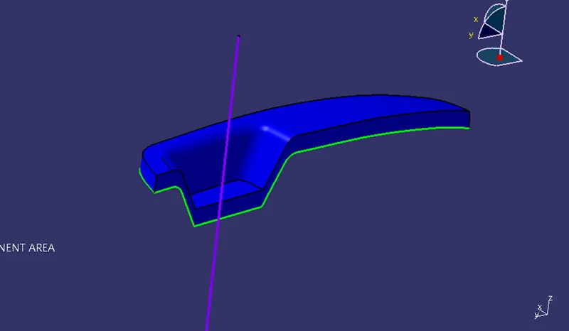
After the extrapolation the Class C Surface is un-hided and then extrapolated 2mm in the upward direction. After the extrapolation it is trim with the initial extrapolated Class A Surface as shown in the figure below.
Now after the trim, the Class B Surface is un-hided and is trim with the earlier trimmed surface hence we get here the parting surface with the component area as shown in the figure below.
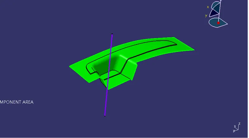
Now our parting surface is fully designed.
The next task is to design the core. Now to design the core a rectangular sketch at the XY plane is drawn and is extruded along the tooling axis as shown in the figure.
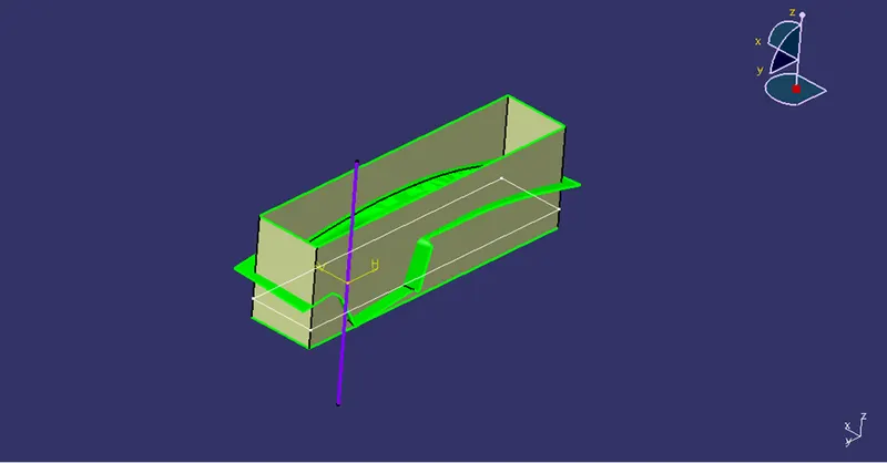
Now as it is extruded the parting surface is trimmed with the extrude and hence we get the core like structure as shown in the figure below.
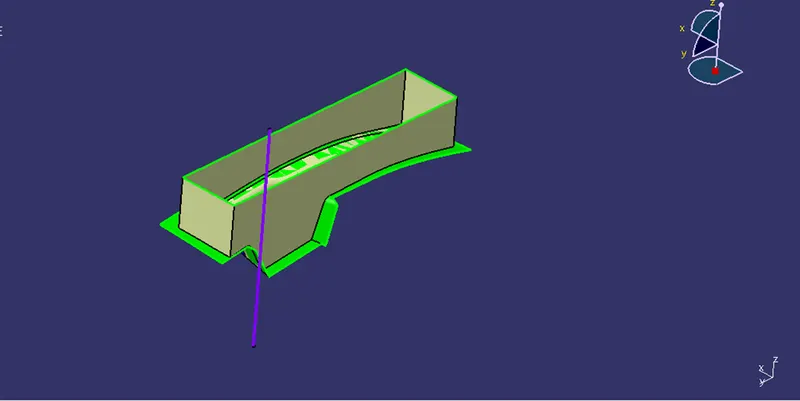
Now the upper surface is open it needs to be closed, so the surface fill command is used to close the surface by creating the boundary and then it is joined together as shown in the figure below.
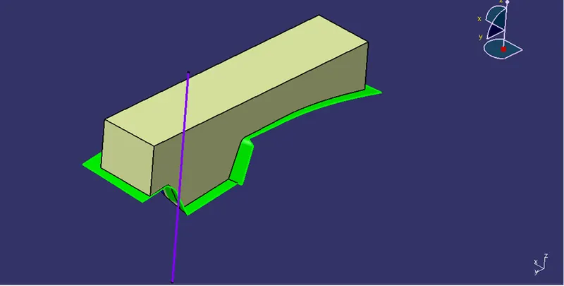
Hence our core is designed.
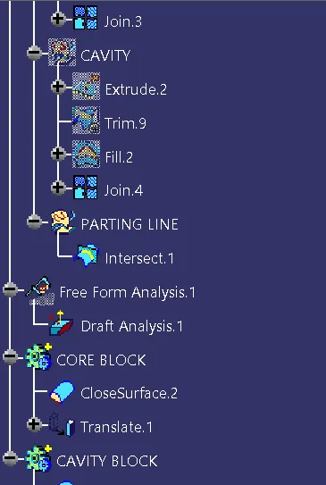
The next task is to create/design the cavity for the switch bezel. So now here again the rectangular sketch is extruded along the tooling axis and then it is trimmed from the upward direction. As it is trimmed from the upward direction the surface fill is created to fill the bottom surface and then it is together joined as shown in the below figure.
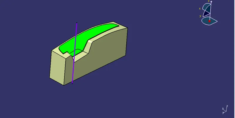
Hence our cavity is designed.
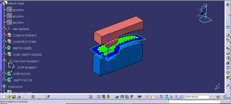
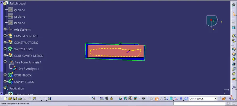
Now to create the parting line. Parting line is nothing but the line that separate the core and the cavity. The parting line here is the intersection of the Class A,C together with the Class B Surface as shown in the below figure. The yellow color line represents the parting line.
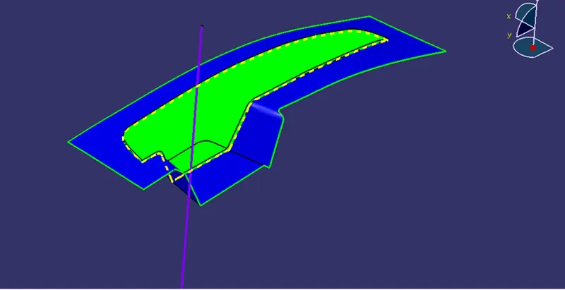
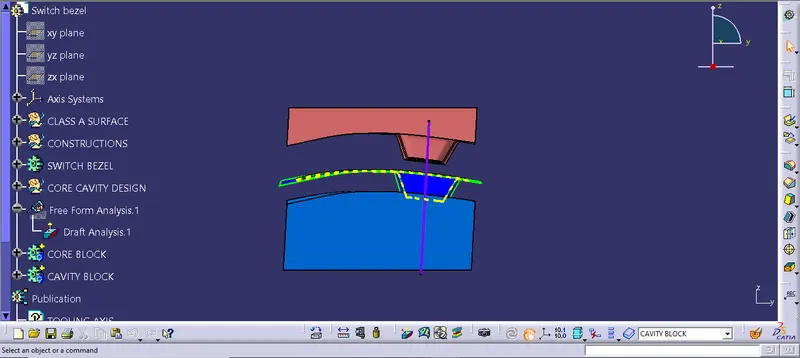
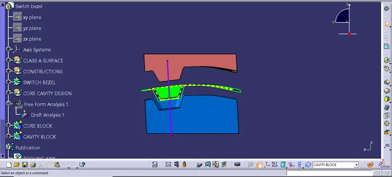
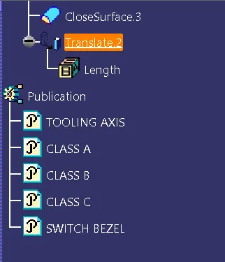
Now as everything is designed the core and the cavity is to be converted into the closed body so the two bodied are inserted and the part design interface is opened. Then the closed body command is use and then the core and then the cavity is converted into the closed body as shown in the figure. The translation command is used to keep the core and the cavity at the distance so that we can get the clear view of about how the core and cavity closes in order to manufacture the component.
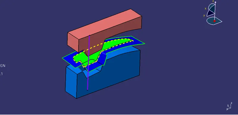
Hence our core and the cavity is designed fully.
Images:-