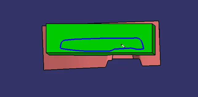
Week 8 - Challenge 5 - Core & Cavity Design
CORE AND CAVITY DESIGN FOR THE SWITCH BEZEL :
The objective of this assignment is to create the Core and Cavity of the Switch Bezel component which was designed in the previous assignments and also identigy the Parting Line and Parting surfaces.
DRAFT ANALYSIS :
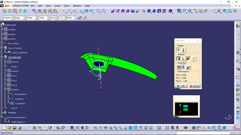
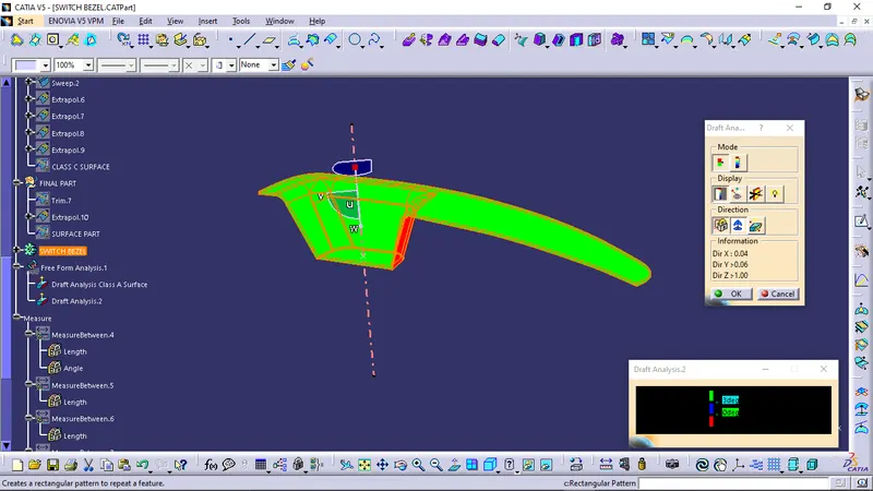
- First we need to perform Draft Analysis on the Class A surface in order to check that the surface is obeying the design rule and proper draft is given to the required faces so that the component is manufactureable and we can easily create the Class B and Class C surface.
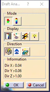
- After creating the solid part we need to check that proper draft angle is maintained in the component or not so that the component can be manufactured.
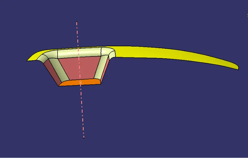
- To perfrom the Draft Analysis we need to create the Tooling Axis first and for that we need to decide which side is the core part and which one will become the cavity part.
- As per visual inspection we have identified the core and cavity side and the direction of tooling.
- Now we need to create the tooling axis by identifying the faces which are tapered and check proper draft angle is maintained or not in order to clear the Draft Analysis.
- First we created a centre point at the base surface and created a axis system at that point.
- Now we have two perpendicular planes and three faces to check whether they clear the draft analysis or not.
- So at first we took one plane and intersected the Class A surface with that plane in order to get the section line so that we can get our tapered lines and using the two tapered lines formed by intersecting the plane we created a bisecting line passing through the same point.
- Then we intersected the Class A surface with the other perpendicular plane in order to get the section line and get the line tapered. After getting the tapered line of the tapered face we created a line at an angle passing through the point to get the tooling axis and defined the angle between the two lines in order to satisfy the draft condition.
- After getting both the lines by intersecting respective planes now we need to bisect these two lines in order to create our Tooling Axis.
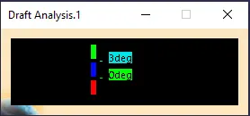
- By following the above method we created our Tooling Axis and Draft Analysis is performed on the Class A Surface.
TOOLING AXIS OF THE PART :
DRAFT ANALYSIS ON CLASS A SURFACE :
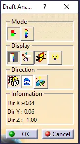
DRAFT ANALYSIS ON SOLID PART :
CORE AND CAVITY DESIGN :
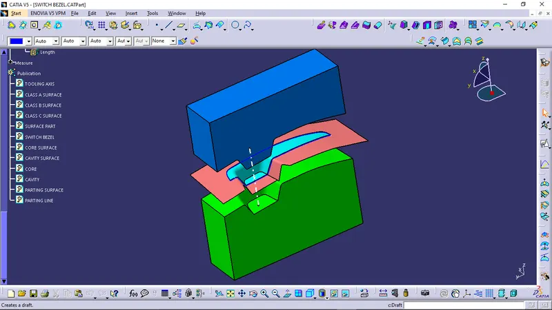
- First we need to identify the surfaces which will be inside the core part and the cavity.
- This can be done using the tolling axis.
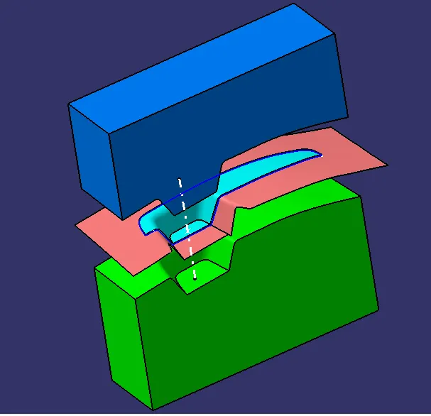
- By selecting the tooling axis and seeing through the normal view the surfaces which we can see from the normal view will be present inside our Core block and the rest surface will be inside the Cavity block.
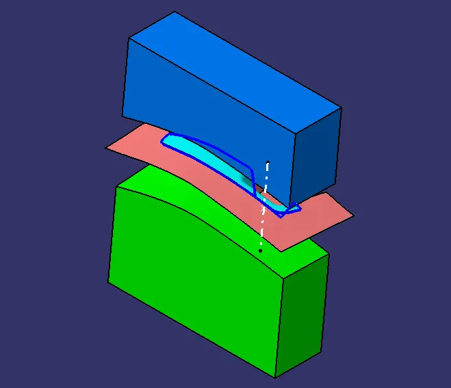
- So our Class A and Class C surfaces will be present inside the Core block and Class B surface will be present inside the Cavity block.
- After creating the Core and Cavity block we need to identify the Parting surface and the Parting Line.
CORE AND CAVITY :
PARTING SURFACE :
- Generally injection mold has two major components the movable halve and the fixed halve.
- During injection molding process these two halves are pressed tightly and form a sealed hollow to avoid the melt flow leakage and maintain certain holding pressure.
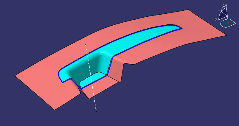
- This pressed surface is called the Parting Surface.
- Usually Parting surface are the biggest projection outline of the part.
PARTING LINE :
- It is the area where the parting surface meets the component.
- It is also the junction between the Core half, Cavity half and the Parting surface.
TREE STRUCTURE :
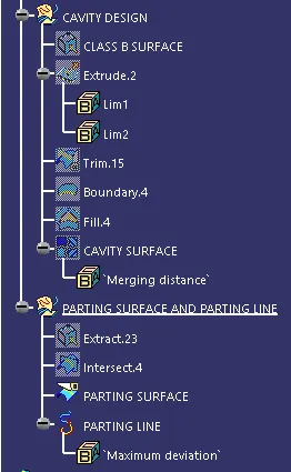
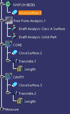
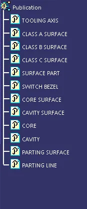
DIFFERENT VIEWS OF THE CORE AND CAVITY :
ISOMETRIC VIEW :
FRONT VIEW :
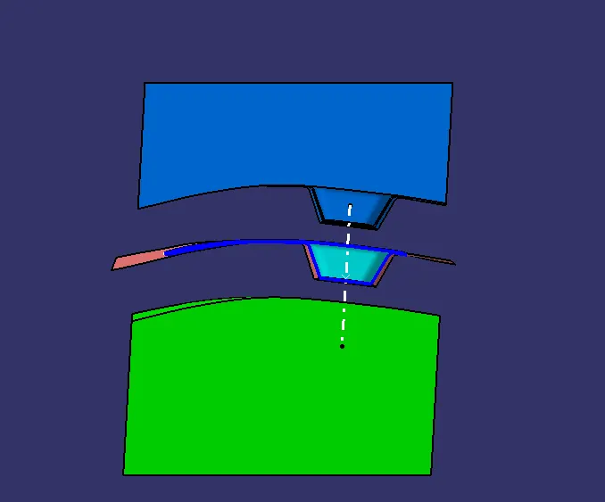
BACK VIEW :
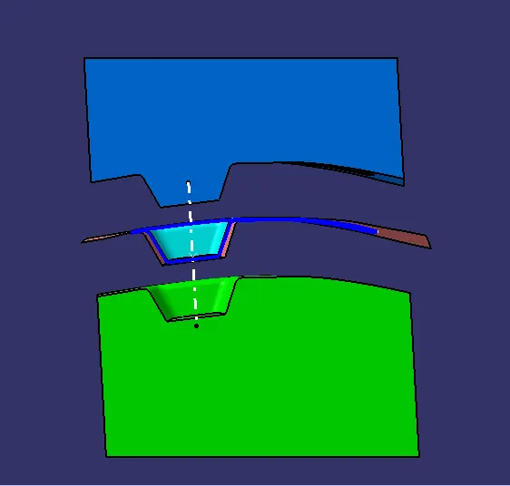
LEFT VIEW :
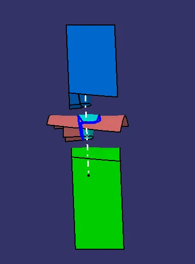
RIGHT VIEW :
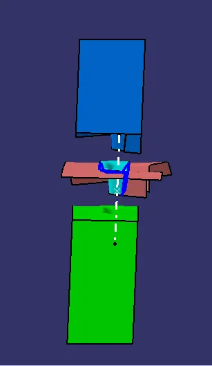
TOP VIEW :
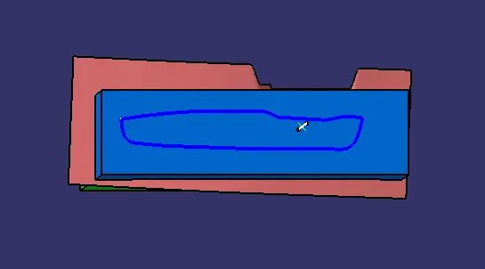
BOTTOM VIEW :