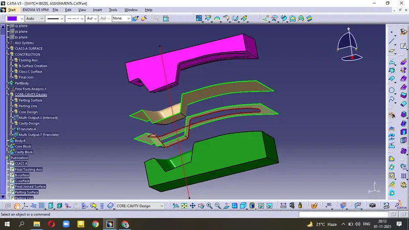
Week 8 - Challenge 5 - Core & Cavity Design
AIM - To create Core and Cavity block of the existing Switch Bezel design
Switch Bezel
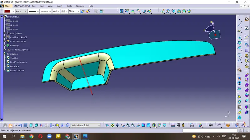
Tooling Axis
The axis through which Core and Cavity is Opened/Closed.
- It is in Red line
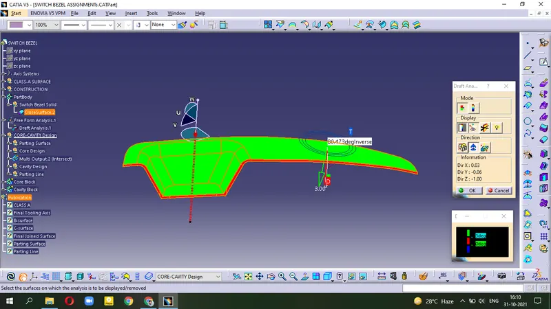
Draft Analysis
Draft Analysis enable us to detect the Part that will be drafted easily or properly during ejection.
- The Core will remove in above side and the Cavity is in below side.
- The Draft angle provided is 3mm.
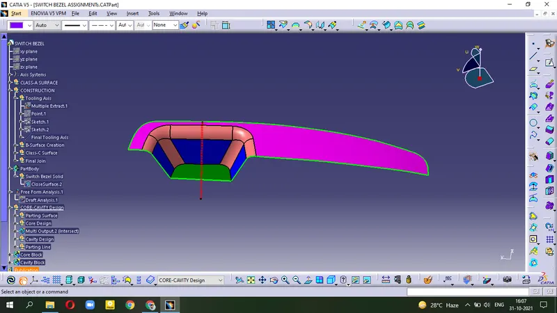
Design Core & Cavity :-
CORE
- It is the movable side of mould, having convex shape in outside.
- Core has the Projection in it
Cavity
- It is the fixed side having concave shape.
- It has depression in it.
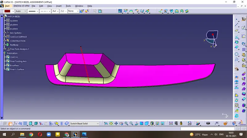
Parting Surface
The Parting surface is the intermediate surface between the Core and Cavity part of the mold. It affects the product quality, construction and operation of mold.
- Design the mold structure simple and avoid/reduce side parting as much as possible to reduce the complexity of mold.
- Ease de-molding. The plastic part should stay in fixed half of mold and it is ejected by ejection system; Avoid side de-molding action.
- Ensure the Dimensional accuracy to reduce manufacturing errors.
- Ensure Class-A should not have parting surface.
- Ensure adequate ventings.
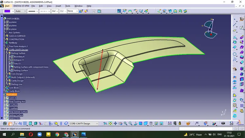
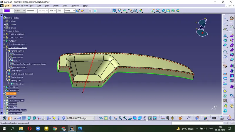
Parting Line
It is the area in which Parting surface and the component meets. In other words, It is the juction between the Core half and Cavity half.
- It should have Class-A and Class-C surface.
- Doted line is the Parting Line.
Procedure
- create Boundary on the Class-a surface.
- Extrapolate the surface
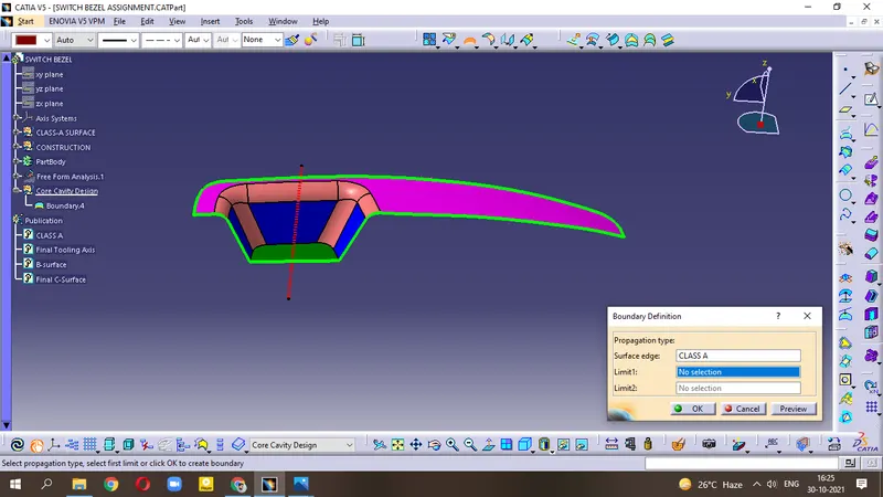
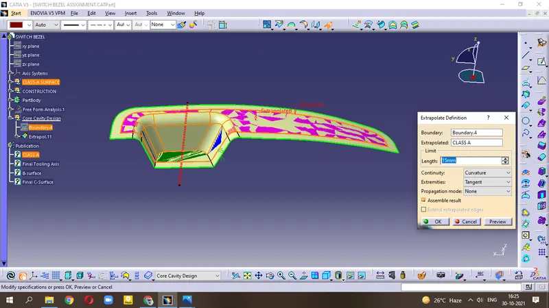
- unhide Class-C surface and Trim this with above Extrapolated surface.
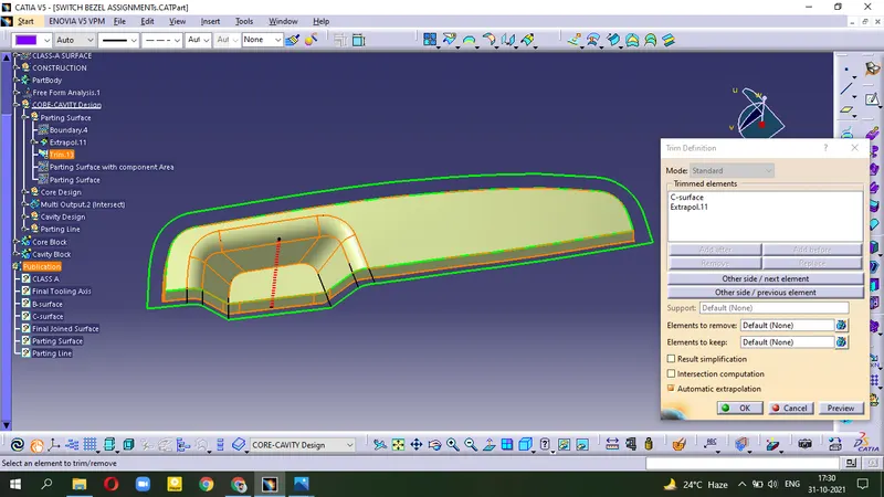
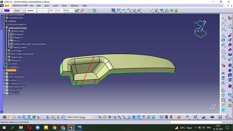
- Trim this surface with Class-B surface.
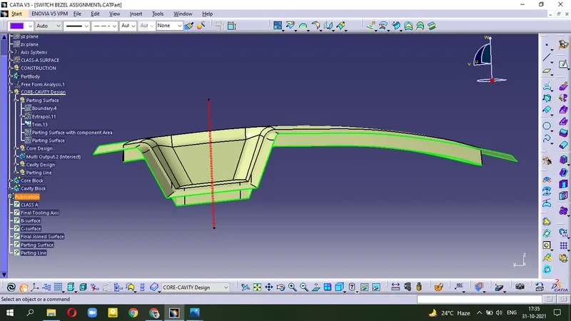
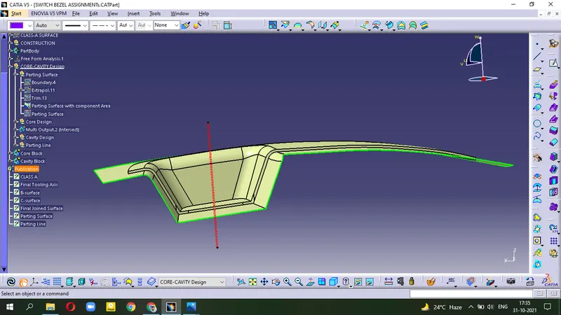
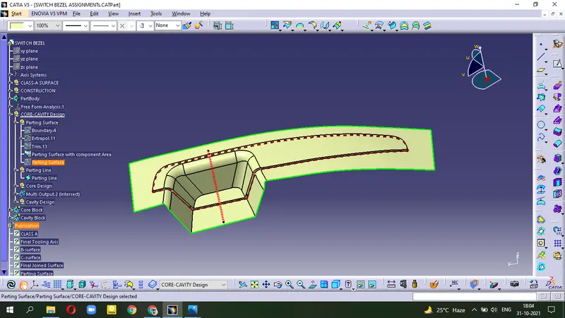
- Split this with Parting Line to get the Parting surface.
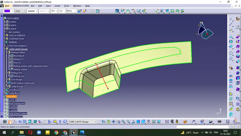
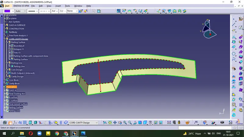
(This is our Parting Surface with Parting Line)
CORE Design :-
- Open Axis system , select the XY-plane and create a Ractangular shape within the Parting surface.
- Check sketch solving status and make it properly iso-constrained.
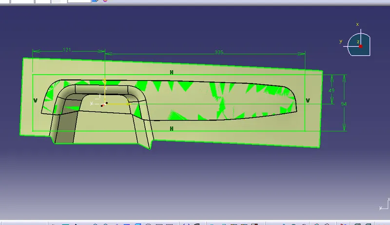
- now, Extrude the Ractangle along Tooling Axis.
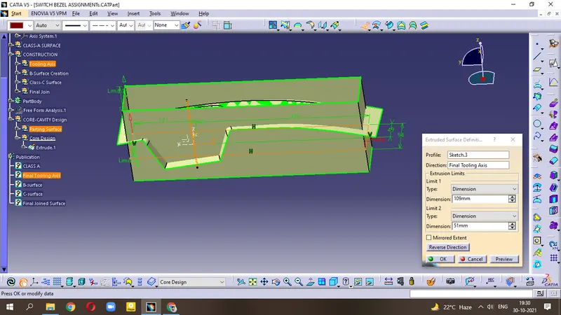
- Trim with the parting surface
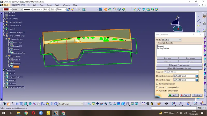
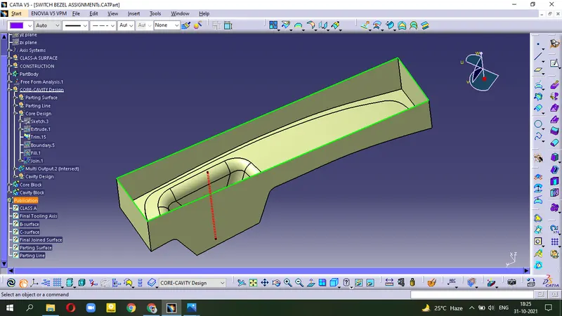
- create the Boundary on above the Ractangular surface and use Fill tool.
- Join together with this Filled surface.
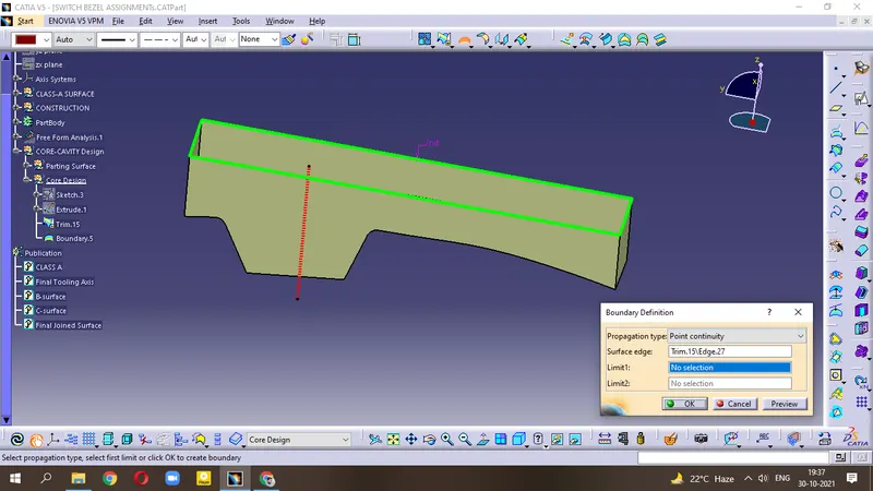
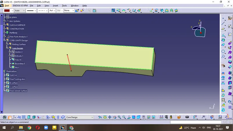
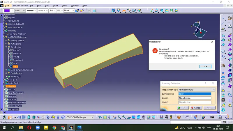
- Now, try to create Boundary on this Joined surface. It is showing Error...
- Our surface is ready to make solid body.
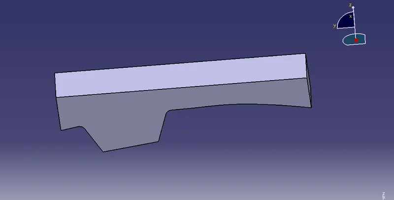
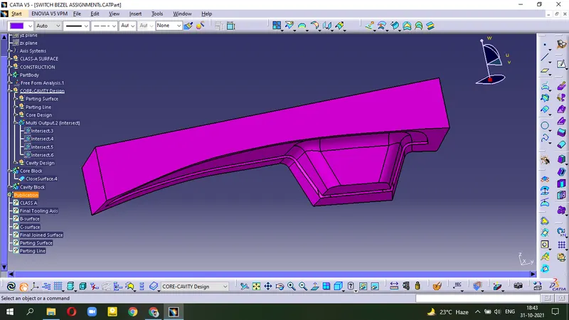
(this one is our Core Block )
- unhide B-surface and make the Intersection in ZX-plane .
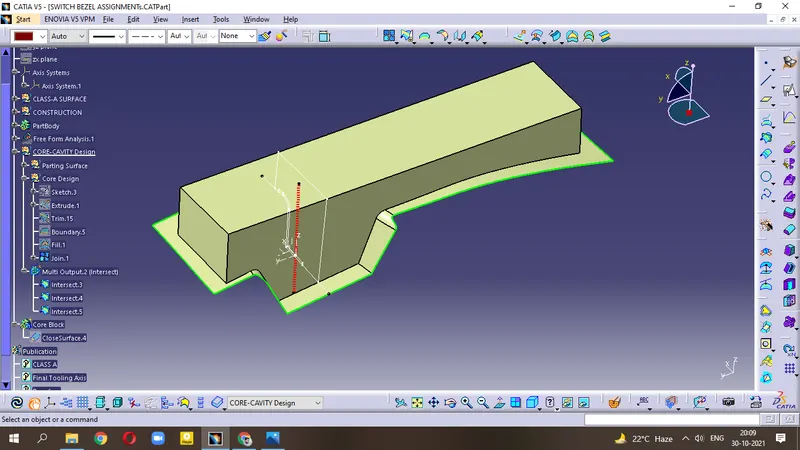
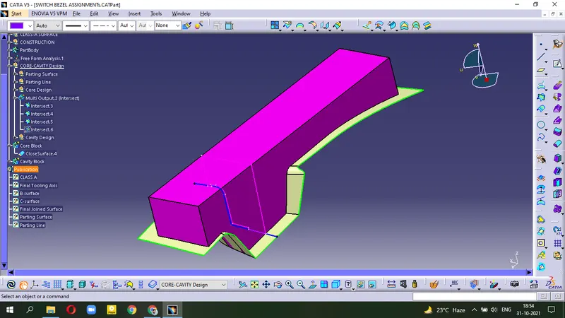
 vds
vds
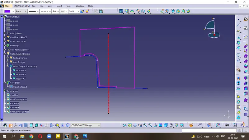
- The Pink line represents the Core surface where vertical line shows the extruded part along Tooling axis.
- Horizontal Blue line represents the intersection of Parting surface.
- The curved Blue & Pink line shows the area where the component formed.
CAVITY Design :-
- unhide the B-surface and Extruded Ractangular surface.
- Trim both surface together
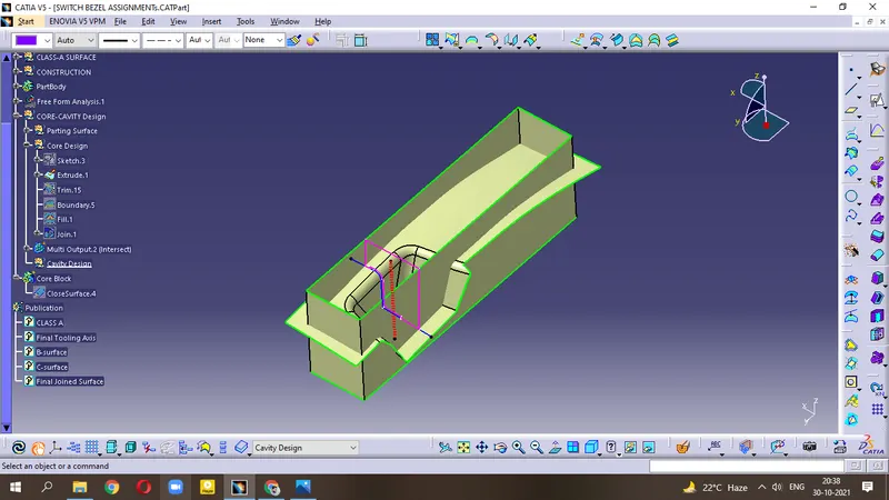
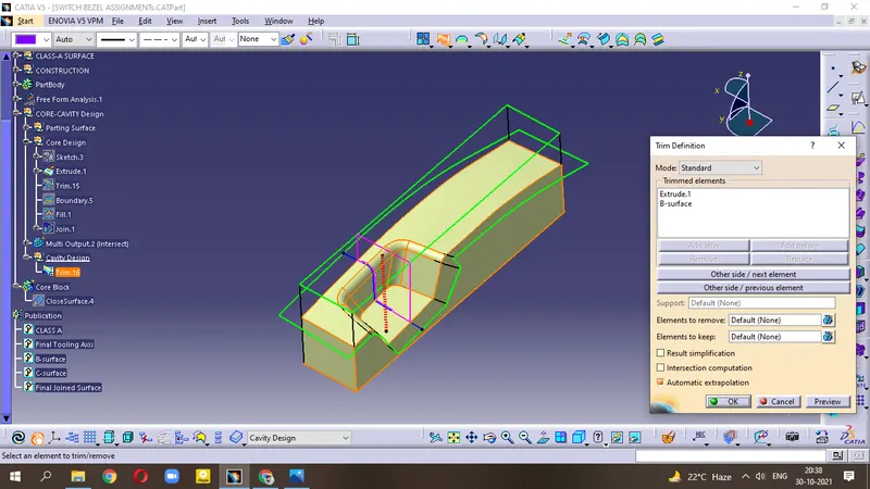
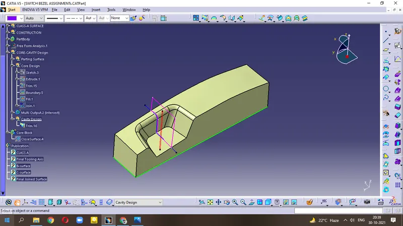
- create the Boundary - Fill - Join
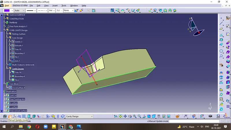
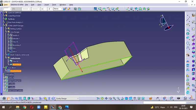
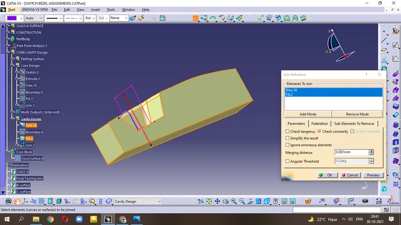
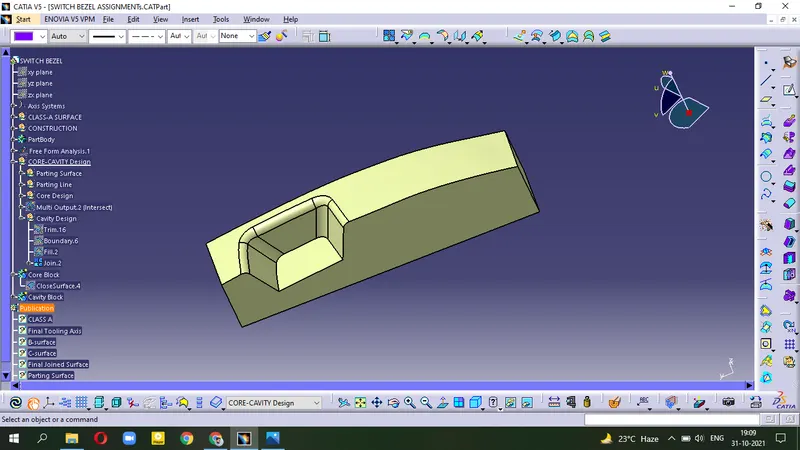
- now, check to create the Boundary over the surface.
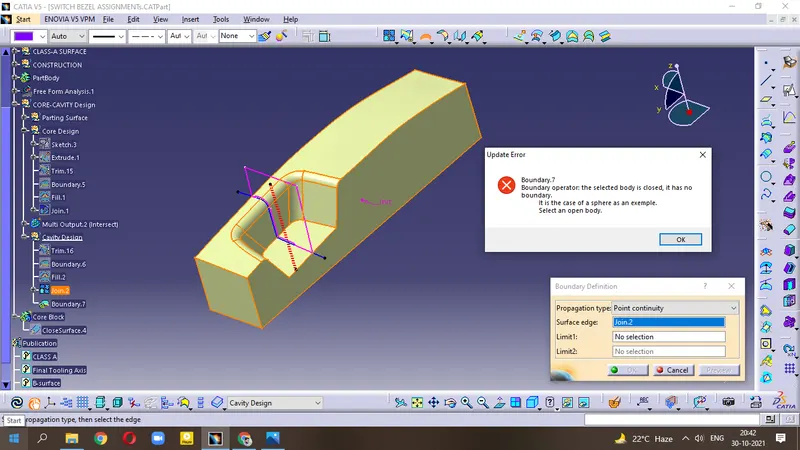
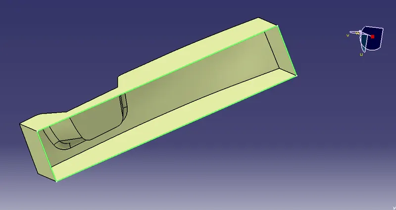
- It is showing Error. so surface is ready to make solid body.
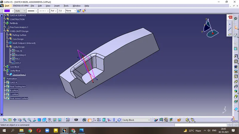
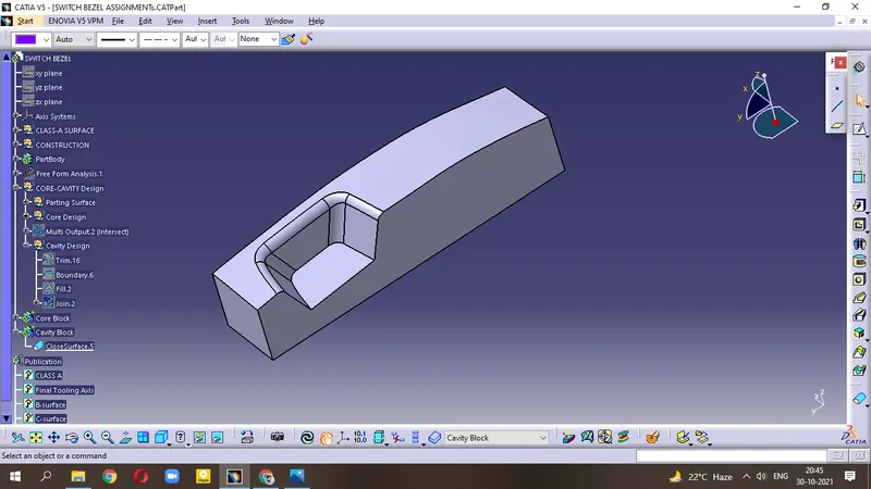
(This is our Cavity block)
NOW
- Unhide the Core Block , Cavity Block , Parting surface, Parting line and Tooling axis.
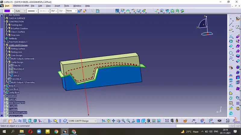
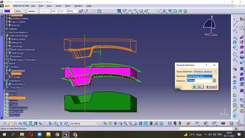
- use Translate to move the blocks
- for Solid Body - Goto Mechanical Design - Part Design - Translation
- for Surface - Generative shape design - Translate
- To Initiate Translation = Right click on Solid body/Surface - Define in work object - Translate by choosing the Tooling Axis.
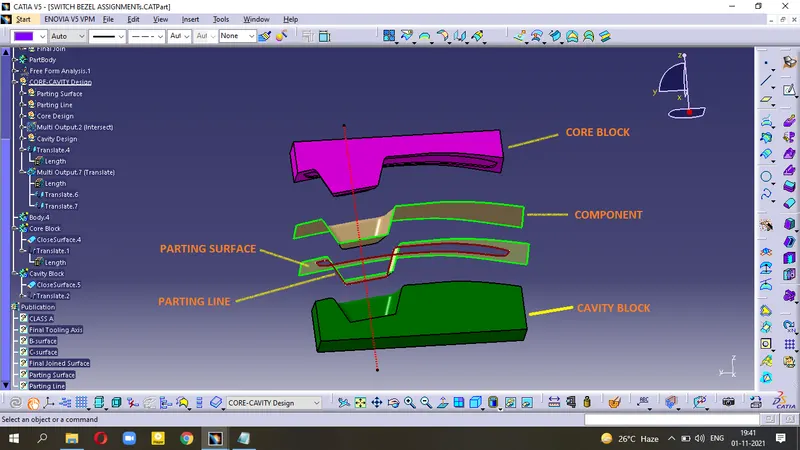
Different View
Front View
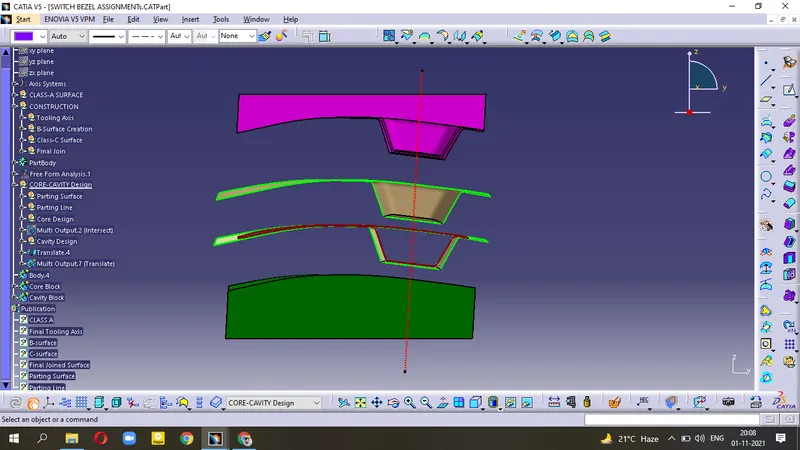
Back View
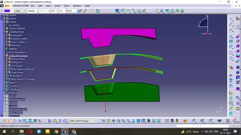
Top View
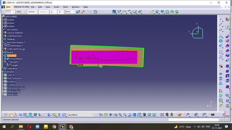
Side View
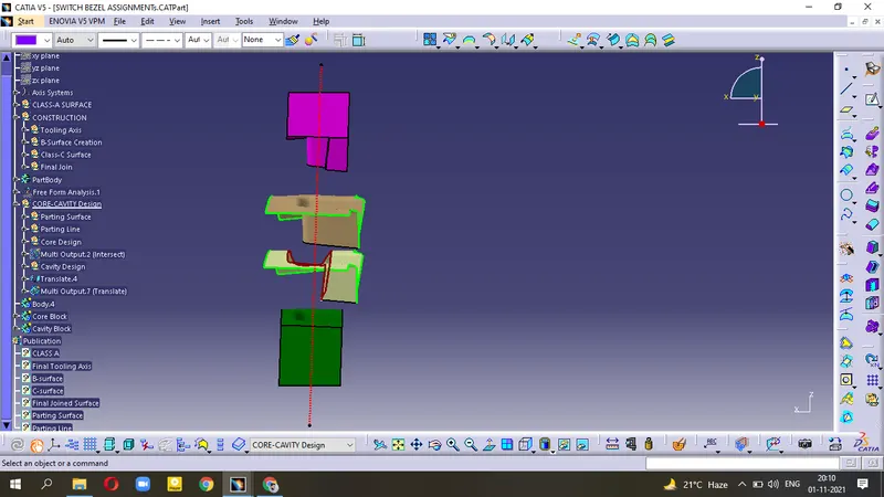
Isometric View