Week 8 - Challenge 5 - Core & Cavity Design
Core And Cavity Design
Aim:-
- To create a switch bezel from the given A-Class surface by considering a thickness of 2.5mm and creating core and cavity block for it.
Tooling axis:-
- To create the tooling axis , we need the proper orientation or view that gicen the correct feature and draft available in the component.
- So here the component view from the Z direction gives the proper view for the tool to see the feature present in the geometry.
- To create the tooling axis from the Z direction we need the tooling axis from the other X direction since it gives the draft available at the slant part.
- The tooling axis created from the X direction.
Parting surface:-
- Generally injection moulding has to major component ,the movable halve and fixed halve. during the injection moulding process ,these two halves are pressed tightly from a sealed hollow to avoid the melt flow leakage to maintain certain holding pressure , the pressed surface are called 'parting surface'.
Surface Creation:
Class A surface:-
- The input of the product designer is in the form of the A-class surface .The job of the product designer is to create the B and C surfaces keeping all the aspects for the mould.
Class A is-
1. Given model in CATprt.
2.Visible surface and aesthetic look.
3.Surface provided by customer (OEM).
4.Class A surface is made by scanned data and different software like alias etc.
5.Surface which is having curvature continiuty is called Class-A.
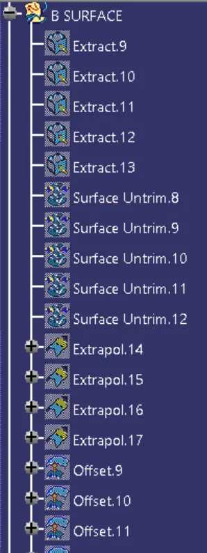
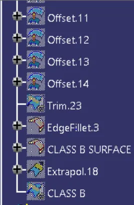
Class B surface:-
1. Invisible surface.
2.surface dont have any structure.
3.surface needs to be created according to the Class A surface,
4.Surface which is having Tangent continuity is called Class-B.
Class C surface:-
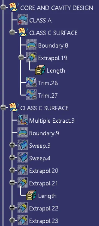
Class C surface has swept along the boundary Class-A surface with respect to the tooling axis direction with a draft angle of 3 degree.
Step By Step Procedure:-
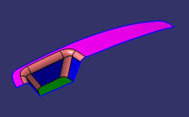
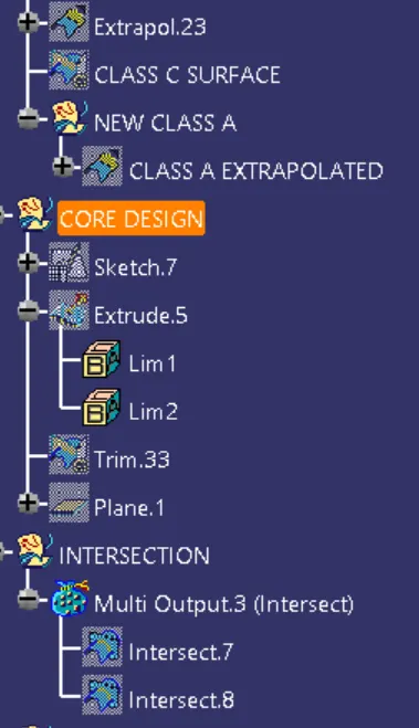
- When you look at the part we have designed the colour highlighted region side is the core side since it have the projection ,here we are extrapolating the Class A ,so that we can use it for trimming purpose while creating core and cavity.
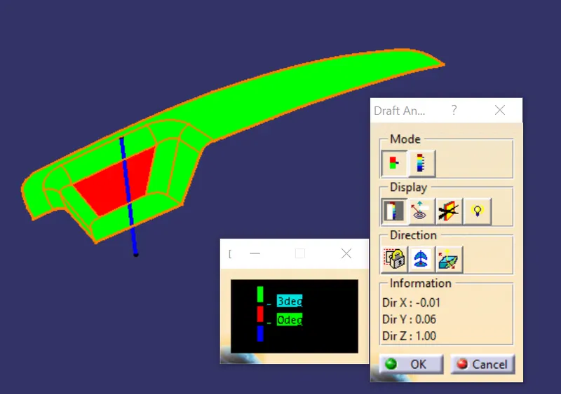
- If we can observe from draft analysis we have done on the component in the previous challenge the surface A and surface C had tooled along A side, i.e "main tooling axis direction".
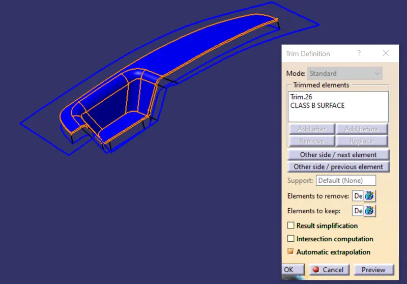
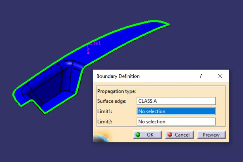
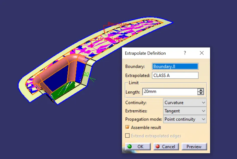
- so we are considering it as a part of core for creating core we need untrimmed class C and class B surface which we crreated before here we are trimming class B with extrapolate class B.
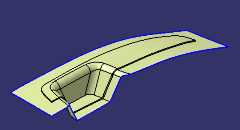
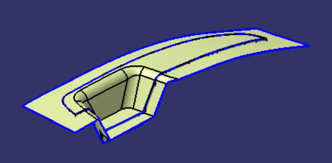
- Now we are creating rectangular sketch so that can cutt off the surface ,while creating we also make sure that boundaries of the sketch is inside the parting surface.
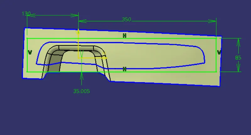
- After the process extrude tool used and extrude it to the suitable height.
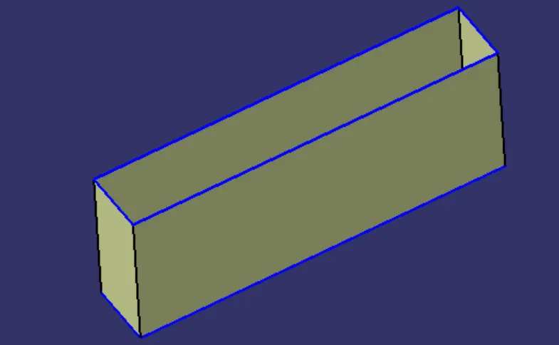
- Later we trim the core along with the parting surface and extrude surface.
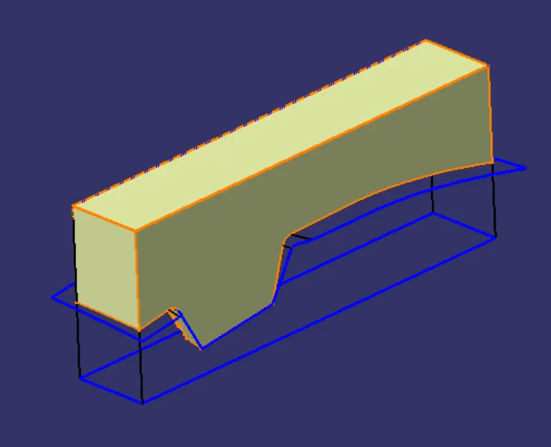
- Use closed surface feature to make a solid body.
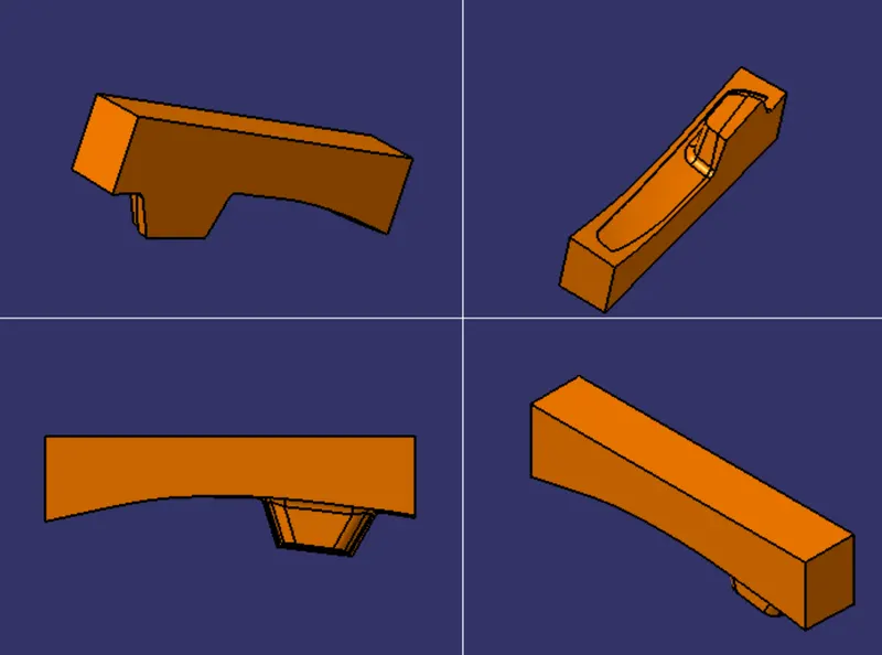
Intersection:-
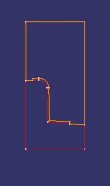
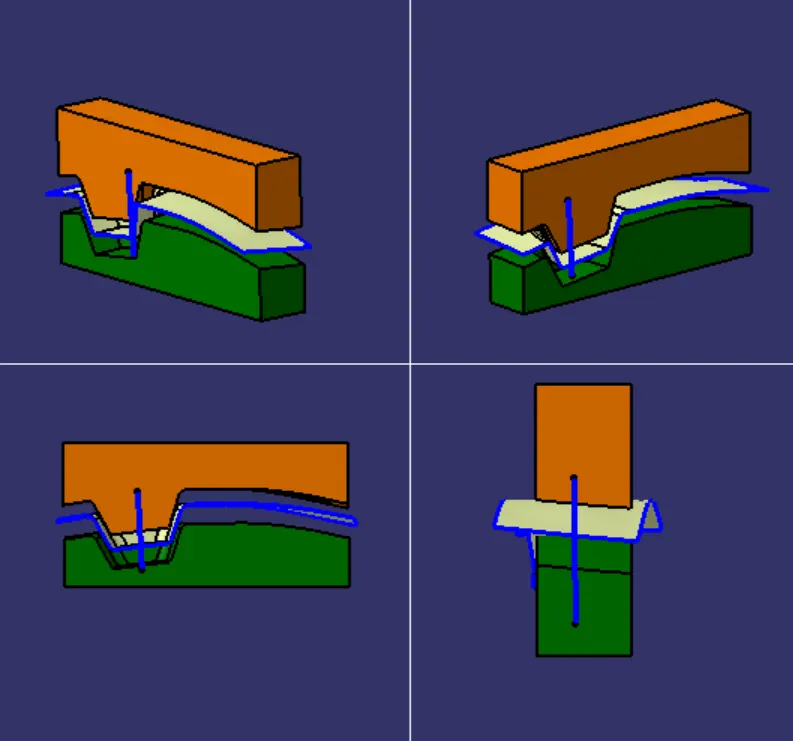
- Here we will use intersection between X plane with parting surface and core, the orange colour shows the core ,where it wall are extruded shows arrow is the parting surface which split core and cavity always ensure to have parting surface on B side, now lets design the cavity .
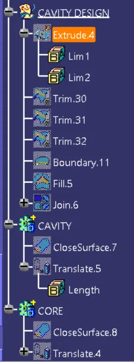
- we follow the same process as above first we will extrude the surface along tooling axis ,we need ignore the component area and rim the body with B surface then the bottom portion to make it closed body for solid block.
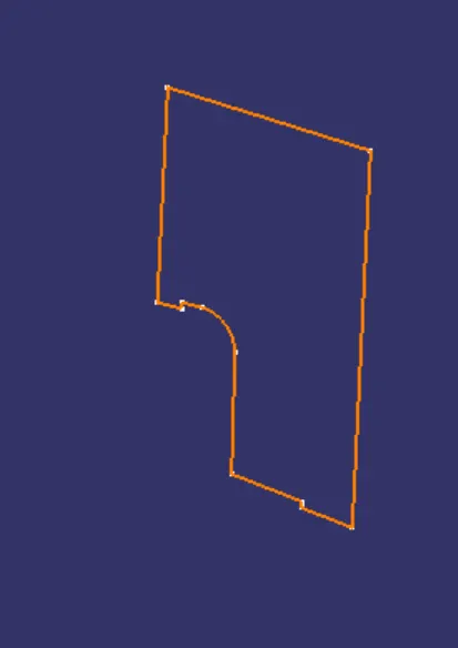
- Here after making cavity block we need the intersection with the axis X again , the below image shows cavity block which is in orange and the arrow mark is parting surface.
- Generally ,injection moulding has two major components, movable and fixed halve .during injection moulding process these two halves are pressed tightly and form a sealed hollow to avoid the melt flow leakage and maintain certain holding pressure,usually parting surface are biggest projection outline of the part.
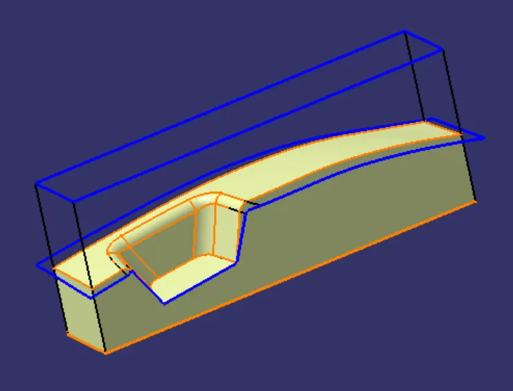
- Use closed surface feature to make a solid body.
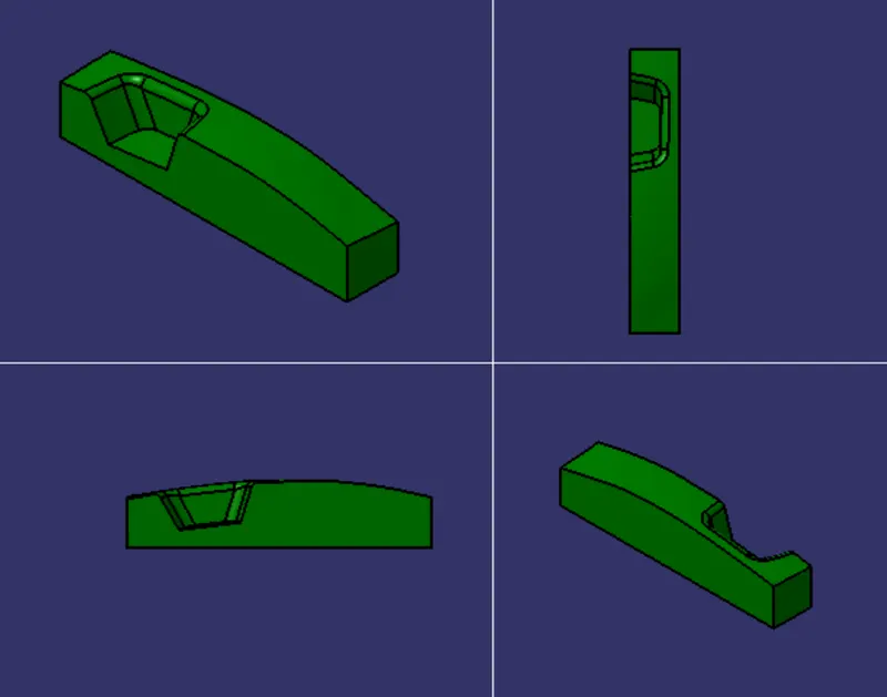
- We have created the parting surface to make sure it easy for creating core and cavity block but parting surface is actually whatever is outside the component area,so split it which gets us actual parting surface.
- Yellow surface shows parting surface.
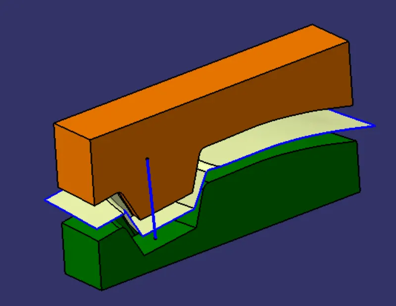
- Finally, we translating the parts seperatly for easily understanding core, cavity and parting surface.
Publication:-
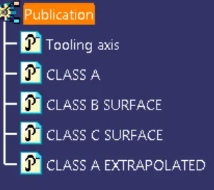
1.Tooling axis.
2.Class A surface.
3.Class B surface.
4.Class C surface.
5.Class A extrapolated.
Result:-
- Finally we created core and cavity blovk design for switch bezel.