Week 8 - Challenge 5 - Core & Cavity Design
CORE AND CAVITY DESIGN- SWITCH BEZEL
Objectives:
- To study the process of the injection molding considering the importance of product design.
- To design mold core and cavity for the manufacturing of a switch bezel solidpart.
- To generate and visualize the different properties of the mold such as parting lines and surfaces.
Software used: DS CATIA P3 V5 - GENERATIVE SHAPE DESIGN, PART DESIGN WORKBENCH.
Introduction:
Here we use the previously made switch bezel part to analyze and study for the manufacturing process of it by injection molding. And hence we will be making the core and cavity parts using the same 3d model. The model is already checked for draft analysis. Different aspects of molding process will be discussed on the specific part considering the injection process.
Methodology/ Approach:
3d part:
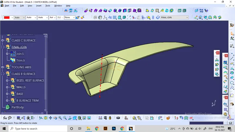
Draft analysis:
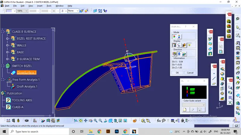
Using the feature draft analysis tool, analyzing the class A and C surfaces for passing the draft angle of 3 degrees. here is the results:
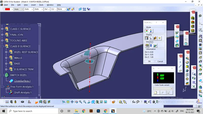
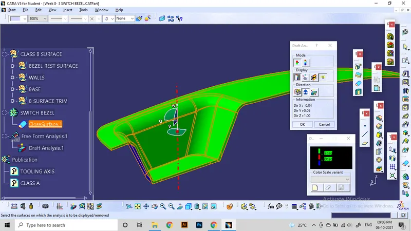
Class A and C surfaces are found to be useful for the molding process with 3-degree draft angle with the tooling axis.
Core block generation:
From the view of the component, we can understand that the surfaces facing top and the surfaces in the depressed region come as core part. and the class c surfaces also covered in the core side ofte mold. so we need these surfaces to construct the core block.
for making the core block, first we need to make the surfaces comes in core side. And from the part, we surely need the class A and C surfaces. along with that we need a extended surfaces from the component to all sides to make the parting surface. Parting surface is the junction between core and cavity part. This surface will help to diffrenciate between core and cavity side.
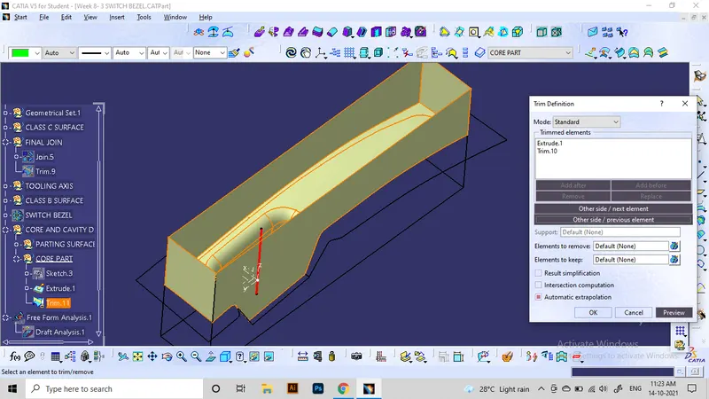
In this case, for the parting surface we can use the extrapolated faces of the class b surfaces. we does not need the class b surface of the component for creating core. It is then trimmed along with the class A and C surfaces as shown here:
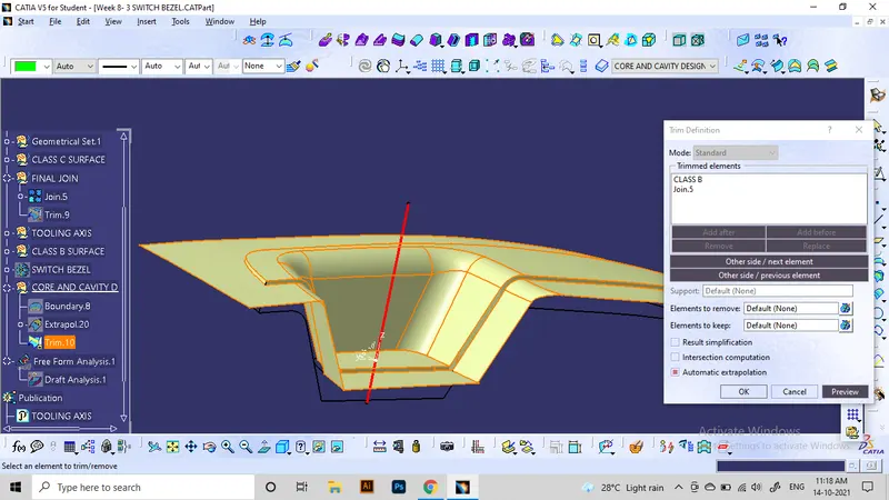
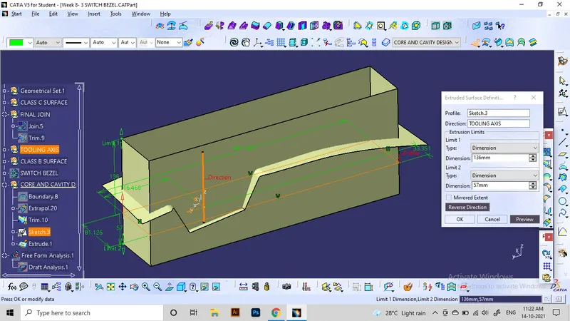
For simplicity of design, we can make the core part as a rectangular block with our core side impression of the component is shaped on one side of the block. Making a rectangle that covers the entire class A and C surfaces and intesecting the parting surface.
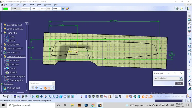
Extruding this rectangle at the tooling axis direction will give the 4 sides of core block.
It is then trimmed with the core side surface at the parting surface and its edge. and the top portion needs to be filled using fill at the opened boundary.
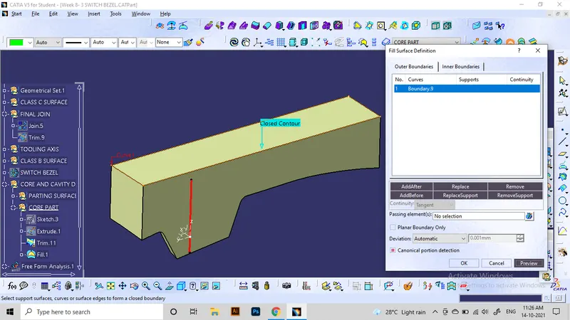
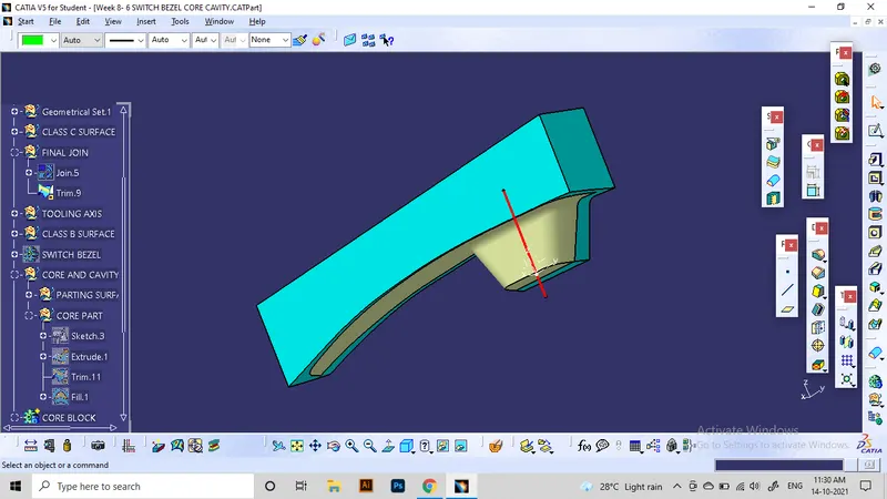
Now the part will have Class A and C surfaces at the bottom side making it the independent 3d model for molding the switch bezel. The surface part can be made to a solid using closesurface command.
This image shows light blue as the core part and component attached to it.
Cavity part design:
A similar method can be used to generate the cavity part. For the design, we only require the Class B surface and parting surface since others are included in the cavity, And we also made the parting surface as the extension of the class B surface.
The same sketch of the rectangle is also used for this application.
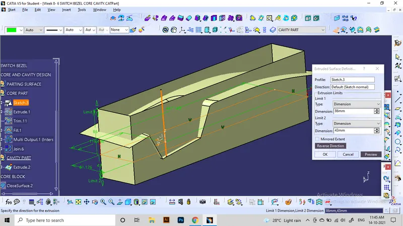
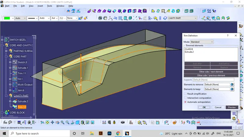
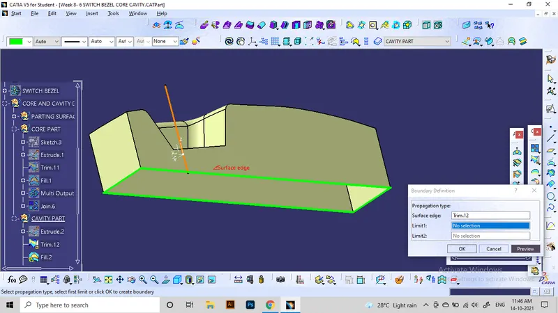
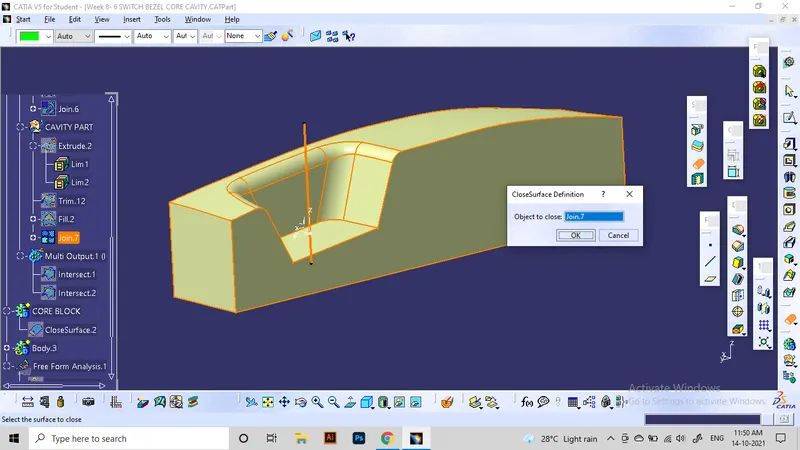
Here shows the attached core and cavity blocks so that you can see there is no gap between core and cavity parts at outer portions.
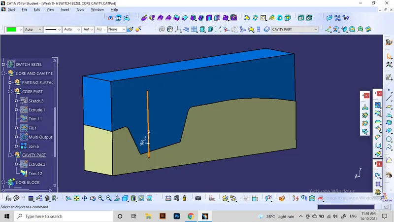
For viewing the inside features, we can use the intersection tool along the ZX plane of axis system. Here we can understand how the blocks come in contact leaving the hollow section to fill plastic for making the solid component.
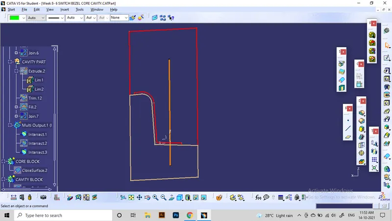
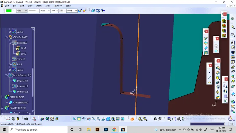
Here is the section view:
Parting line:
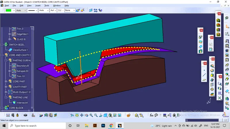
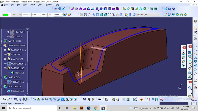
The intersection of the component and the parting surface is known as the parting line. In this project, a parting line can be made by intersecting the parting surface with the patch joined using class A and B.
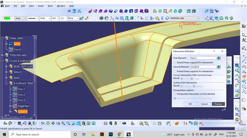
Final outcome:
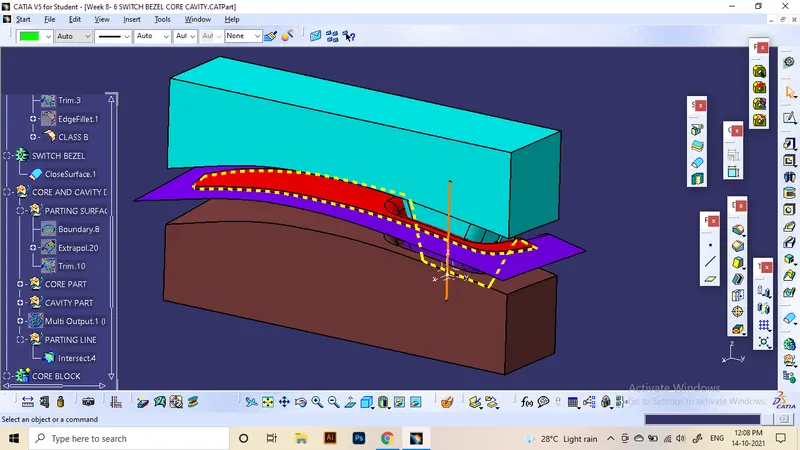
hence the required aspects of the core and cavity design is completed as shown here.
light blue: Core part
Brown: Cavity part
Red: Component
violet: Parting surface
Yellow: Parting line
Orange: Tooling axis