Week 8 - Challenge 5 - Core & Cavity Design
AIM:
To create a switch bezel from the given A-class surface by considering a thickness of 2.5 mm and also creating Core and Cavity blocks for it.
PROCEDURE:
A class surface :
The input of the product designer is in the form of the A-class surface. The job of the product designer is to create the B and C surfaces keeping all the aspects for the mold.
Class A is
1.Visible surface and aesthetic look
2.surface with textures
3.Surfaces provided by customer(OEM)
4.Don't have any features like(rib, snap, bosses, etc) on class A surface.
5.Class A surface is made from scanned data with different software like alias etc.
6.Surfaces which have CURVATURE CONTINUITY IS CALLED class-A.
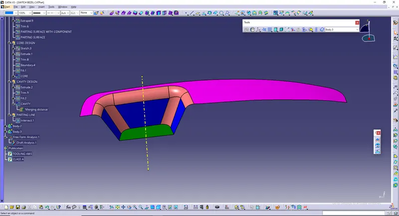
B class surface:
Class B surface:
1.invisible Surfaces.
2.Surface mostly don't have textures
3.Surface needs to be created according to the class-A surface.
4.having all features(Rib,boss,snap etc) in B-side surface only.
5.Surfaces which is having TANGENT CONTINUITY IS CALLED class-B
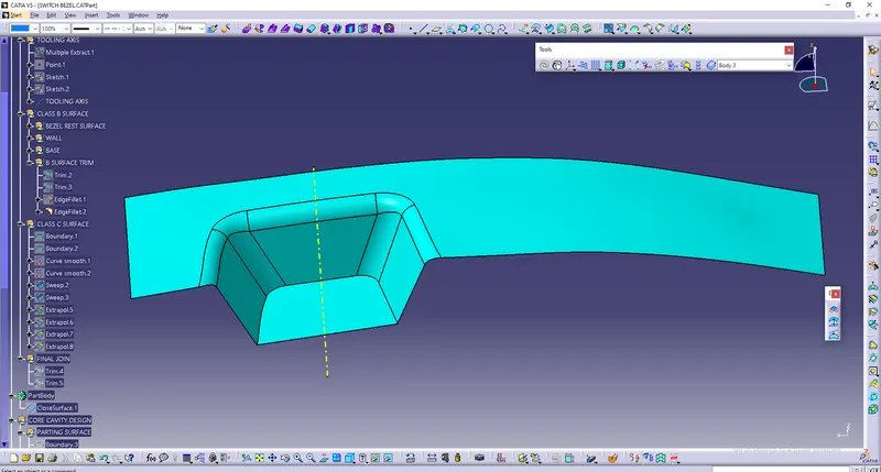
C class surface :
Class C Surface has swept along the boundary CLASS A surface with respect to the tooling axis direction with a draft angle of 3 degrees.
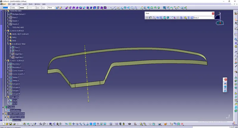
Final switch bezel component:
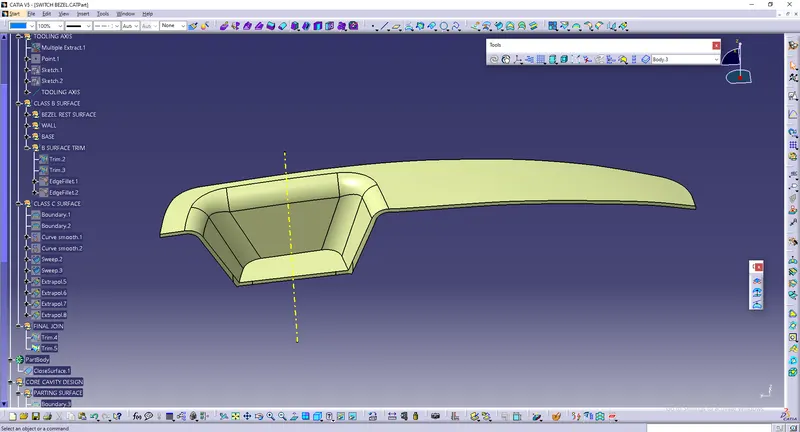
Tooling axis :
- To create the tooling axis, we need the proper orientation or view that gives the correct features and draft available in the component.
- So here the component view from the Z direction gives the proper view for the tool to see the features present in the geometry.
- To create the tooling axis from the Z direction we need the tooling axis from the other X direction since it gives the draft available at the slanted part.
- The tooling axis created from the X direction by following steps
- The base surface is extracted.
- Then the center point is created using the point > on the surface at 0
- At the point created the axis system is created
- After that switching the view of the model to the X direction and creating the tooling axis.
Using the intersect in the ZY plane to get the boundary lines.
Then the lines are created along the slant surfaces.
Then these two lines are bisected to get the tooling axis for the X or the final
- Next, switching in the Y direction and intersecting the switch bezel part in the ZX direction to get the intersecting lines.
- Using the axis center point, a line is drawn in sketch mode and it is constrained at the angle of 4 degrees. (this angle value is an arbitrary value and can be changed to get the final tooling axis that provides a positive draft )
- At last, both the lines are bisected to get the final tooling axis.
Draft analysis :
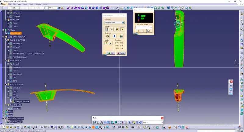
Click the (Feature) Draft Analysis icon:
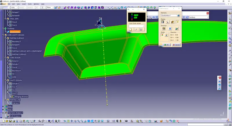
- The Draft Analysis dialog box is displayed. It gives information on the display (color scale), the draft direction, and the direction values.
- The Draft Analysis.1 dialog box showing the color scale and identifying the maximum and minimum values for the analysis is displayed too.
Mode option
- The mode option lets you choose between a quick and a full analysis mode. These two modes are completely independent.
- The default mode is the quick mode. It simplifies the analysis in that it displays only three color ranges.
- Enter a new value (negative values are allowed) to redefine the color scale, or use the slider to position the distance value within the allowed range, and click OK.
- The value is then frozen, and displayed in a green rectangle.
- The color scale settings (colors and graduated values) are saved when exiting the command, meaning the same settings will be applied when you will edit a draft analysis. New settings are created with each new draft analysis.
- When the draft angle value of the surface is equal or smaller than a graduated value, the color below the graduated value is applied.
- When the draft angle value of the surface is greater than the greatest graduated value, the color above this graduated value is applied.
- Exit the dialog box.
Display option
- Uncheck the Color Scale checkbox to hide the Draft Analysis.1 dialog box, this dialog box only appears in edition mode.
- Activate the On the fly checkbox and move the pointer over the surface. This option enables you to perform local analysis.
- Arrows are displayed under the pointer, identifying the normal to the surface at the pointer location (green arrow), the draft direction (red arrow), and the tangent (blue arrow). As you move the pointer over the surface, the display is dynamically updated. Furthermore, circles are displayed indicating the plane tangent to the surface at this point.
Core and cavity design:
The Mould Core & Cavity are the shaped sections in either half of the mould tool which give the plastic product its final shape.
The hot molten material is injected into the core & cavity and then sets hard into shape. The design of the core & cavity is essential in the correct formation of the product. The sequence of events during the injection mould of a plastic part is called the injection molding cycle.
The cycle begins when the mould closes, followed by the injection of the polymer into the mould cavity.
A core is usually made of the best quality sand and is placed into the desired position in the mould cavity. Core prints are added to both sides of the pattern to create impressions that allow the core to be supported and held at both ends.
Core :
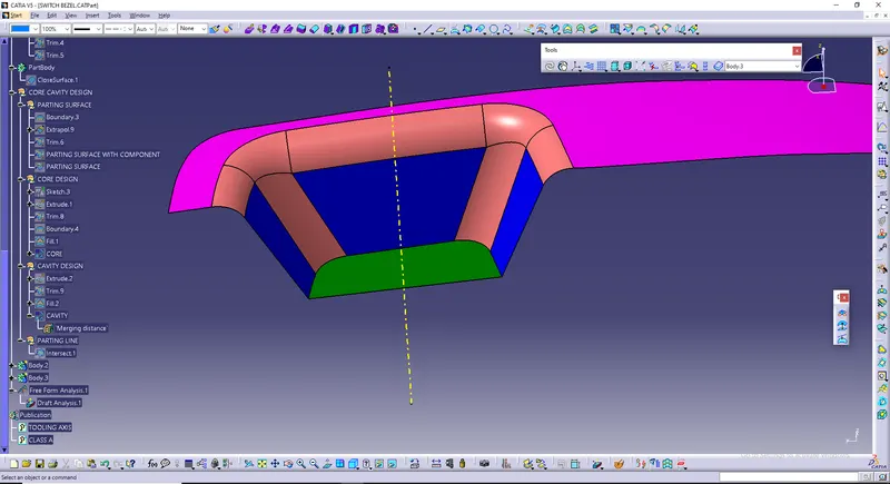
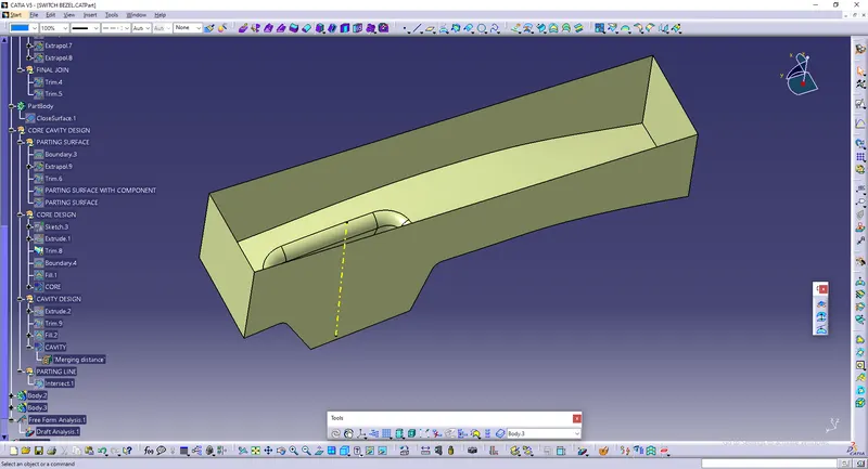
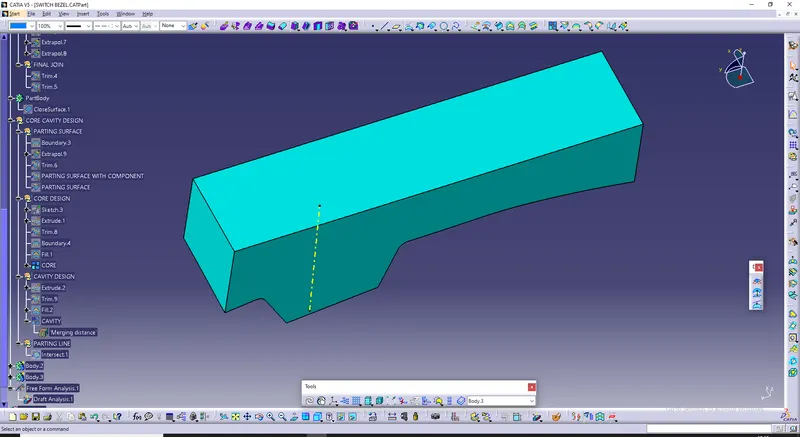
- The core design is started with extracting the parting surface that becomes the datum for the core and cavity. The parting surface in most of the cases is kept at the B class surface to avoid close and tight contact between the core and cavity.
- At first, the A-class surface is extrapolated with some length and later it is trimmed with a C surface
Cavity :
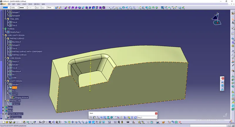
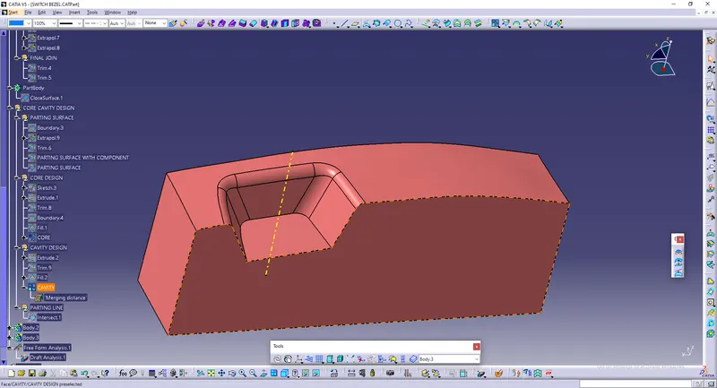
- The cavity is the part where the injector and filling of the molten plastic happens. The cavity block is prepared by first extruding the outer boundary along the tooling direction.
-
This outer surface is trimmed with the B class surface and then it is filled and thickened.
Parting line and Parting surface :
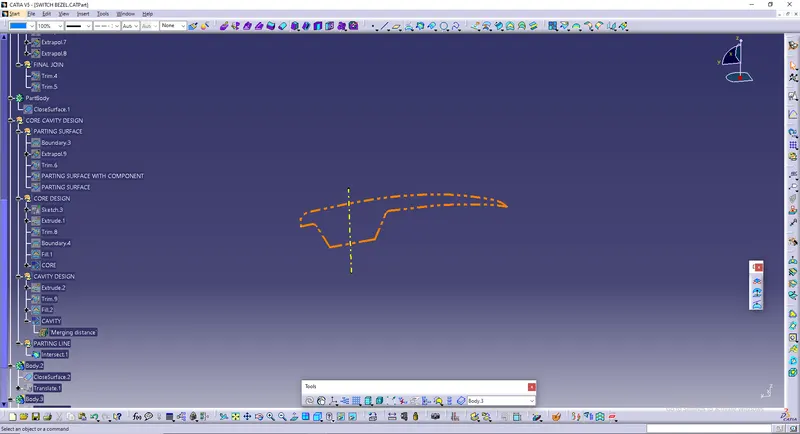
A parting line, in the industrial casting of molds, is the borderline in which draft angles change direction. That is, it is the dividing line that splits the core and cavity halves of a molded part. It is sometimes a starting point for the mold parting surface.
Here intersecting the parting surface, core, and cavity across the ZX plane gives the intersecting line that tells the parting line.
Parting surface:
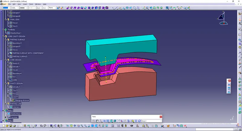
The parting surfaces of a mould are those surfaces of both mould plates adjacent to the impressions which butt together to form a seal and prevent the loss of plastic material from the impression. The parting surfaces of a mould are those portion of both
mould plates, adjacent to the impressions, which butt together to form a seal and prevent the loss of plastic material from the impression.
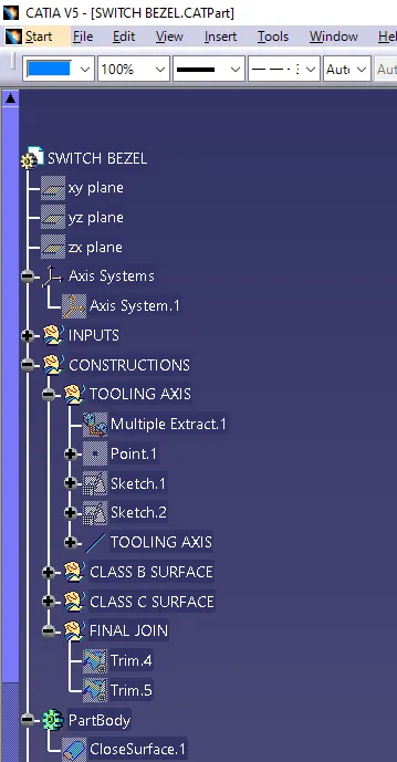
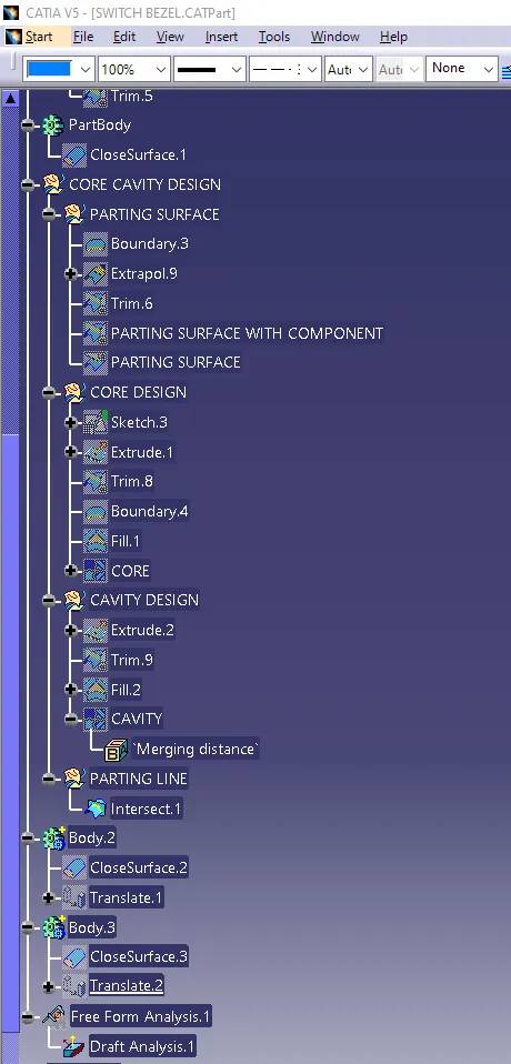
Tree Structure: