Week 8 - Challenge 5 - Core & Cavity Design
Objective
The main objective of this project is to create the core & cavity design and the draft analysis for the Switch Bezel using Catia V5.
Introduction:
The draught analysis will indicate the body's vital angles, and it's critical to keep a favourable draught angle. A draught analysis is performed on a part to ensure that the component can be easily removed from the mould once it has solidified. The parting surface here is made for the good finishing surface side, it is the side where the parting of an object and core takes place, thus the part after solidification can be ejected easily. The core and cavity design are made to get the part manufactured in an accurate manner, the core is the projected side and the cavity is the depressed side, the parting surface here is made for the good finishing surface side, it is the side where the parting of an object and core takes place, thus the part after solidification can.
Methodology approach:
The class A surface is the first crucial input for creating tooling axes and draught analysis, followed by Catia V5. Create the tooling axis and draught analysis by first determining the optimum direction (X, Y, Z) and selecting the direction that is the most straightforward to make. The Tooling axis's Z direction is chosen. If necessary, build a dummy tooling axis in the Z direction using the point as a reference.
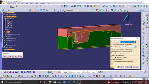
- Create a plane in the ZY direction on the reference point, then an intersecting curve of the switch bezel's ZY plane. Create two lines and bisect them to acquire the tooling axis by bisecting the two lines at an angle.
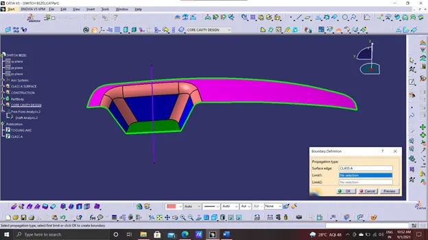
- Use the publish option to publish the Class A surface and the tooling axis, so to use them easily at creating some features.
- Extract the class a surface.
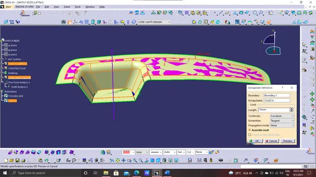
- Then extrapolate the class A surface
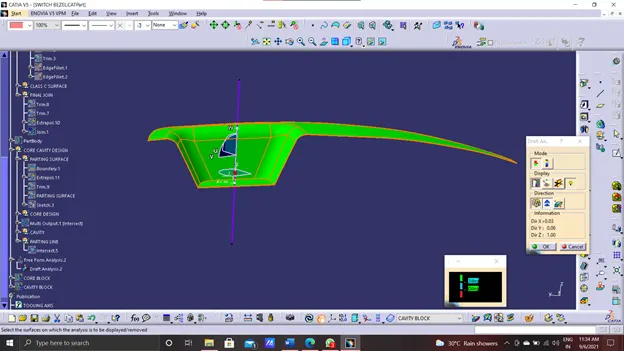
- Make use of the research. To check the draught analysis, there is a draught analysis toolbar. Place the compass in the Z direction line, which is upwards, and lock it.
- Select the axis and the part so that the colour changes in accordance with the tooling axis reference.
- Green, red, and blue are the three hues available in the rapid analysis mode. We can adjust the values to suit our needs, but keeping the typical drafting angle of 3 degrees in mind is a good idea.
- Analysis on running point - this option allows you to quickly analyse the angles at each point.
- The closed surface of the switch bezel is subjected to a draught analysis. The core and cavity are constructed in such a way that the projection side is considered, followed by the creation of a core block.
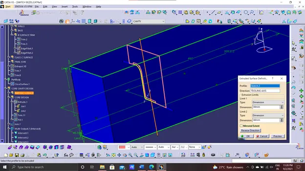
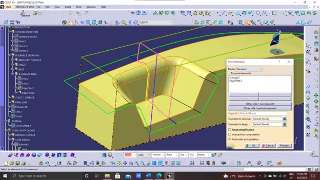
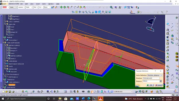
- Sweep the surface and then Trim the surfaces as shown.
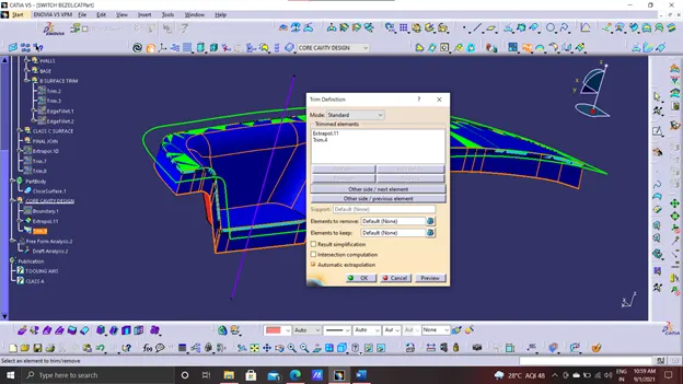
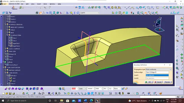
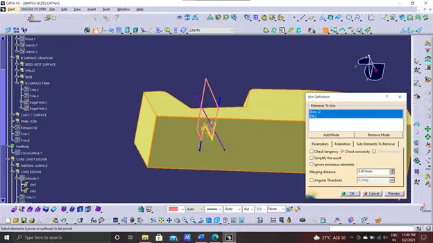
- Now trim it with the parting surface.
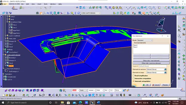
CORE and CAVITY:
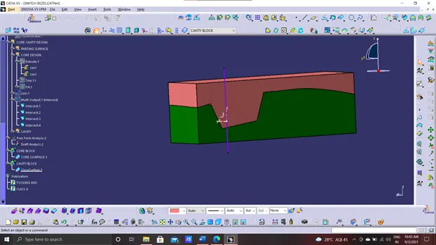
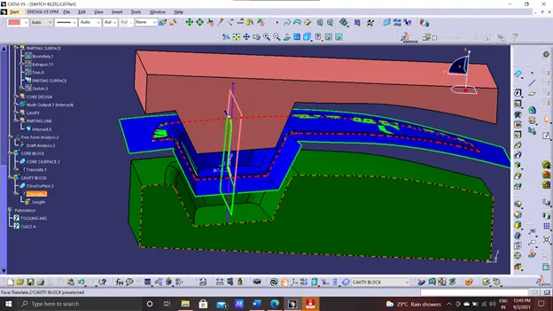
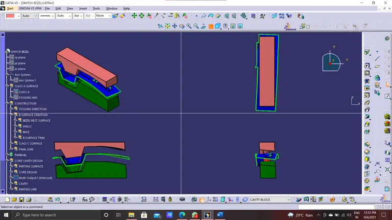
- Core is a moving object travels with the tooling axis s-direction to close with the cavity thus creating the desired part required. Its a moving part RED part is the core as shown below
- Cavity is a fixed part, this is wher the core closes it high pressure with the cavity to shape the part inside of it. Green part is the cavity as shown below.
- There will be created a small hole in core and cavity to ventilate the air present inside the gap between the core and cavity and to remove the component from cavity using pins respectively,
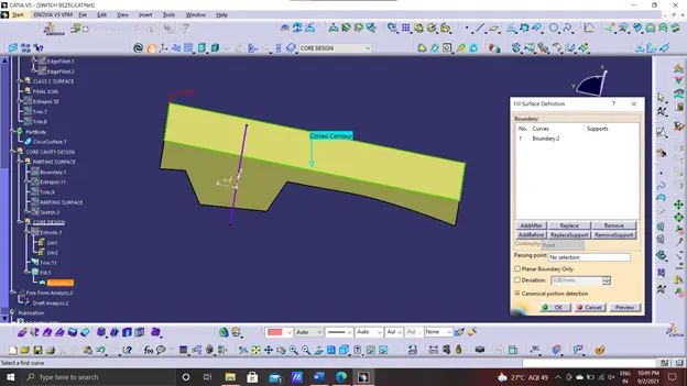
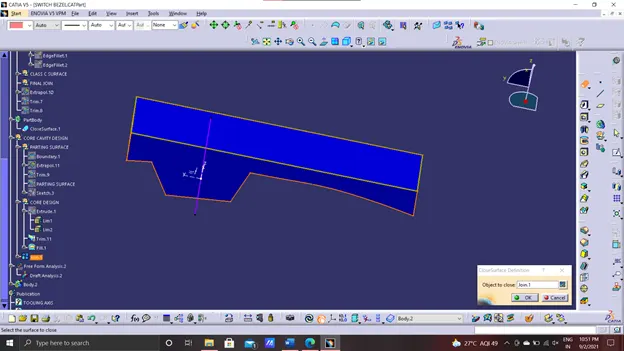
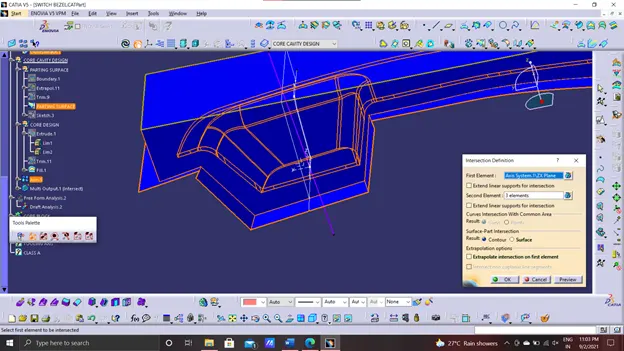
- Now creating the core part
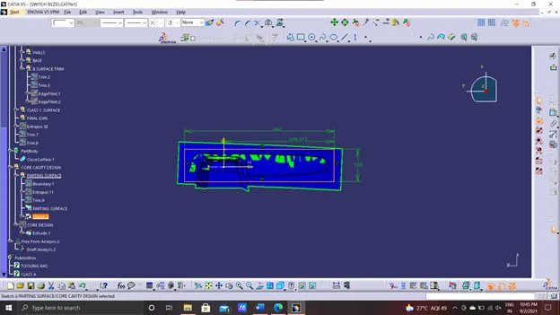
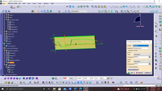
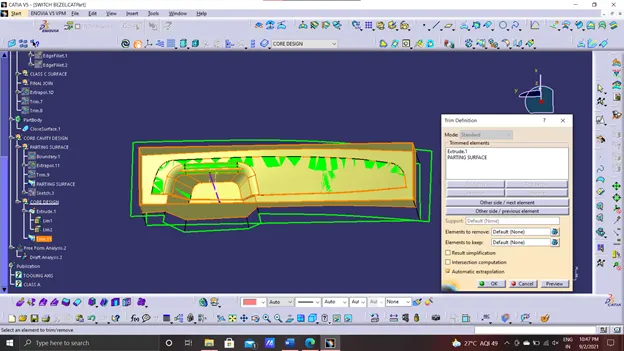
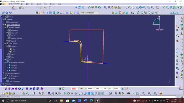
- Now creating the cavity part.
Geometrical sets
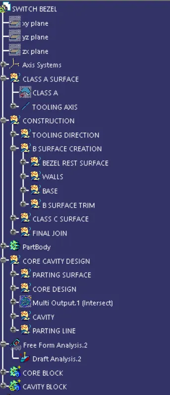
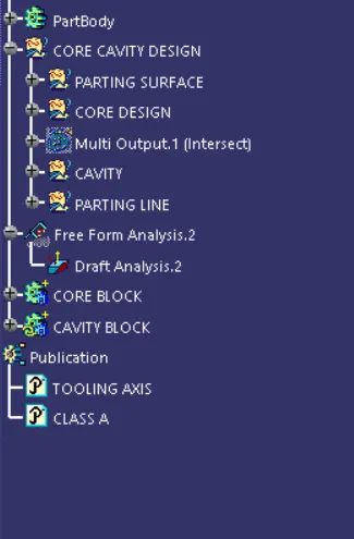
core and cavity blocks in various orientations:-
Conclusion:-
The core and cavity design, draft analysis, tooling axis, B surface and surface are created for the class A surface of the switch bezel