Week 8 - Challenge 5 - Core & Cavity Design
Procedure To Create the Core & Cavity of Base Bracket
Step -1: - To create the core and cavity blocks check the Draft analysis for the final component so that you will get an idea how to create the core and cavity blocks for that component.
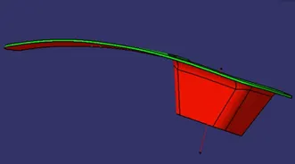
Step -2: - start with extrapolating the class-A surface for that create a new geometrical file and name as Core & Cavity Design in that file add another geometrical file and name as parting surface and extrapolate the class-A surface into the extraction of 15mm and trim the surface with C-surface and get a final trim with B-surface so that the parting surface of the component was formed.
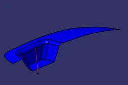
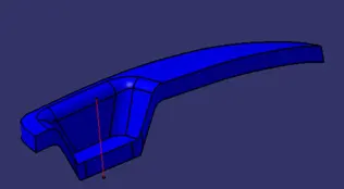
Parting surface: - The surface that separates the core and cavity into two parts there are different types of parting surfaces are there
- Flat or straight parting surface
- Stepped parting surface
- Angled parting surface
- Complex or profiled parting surface
For this component I a flat parting surface is needed, in any case, try to use a straight parting surface it will save time and cost-effectively
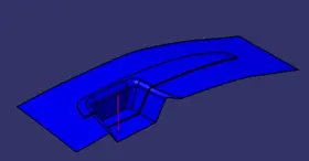
Step -3: - After the creating of the parting surface. Draw a rectangular sketch the cover the complete component
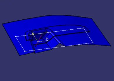
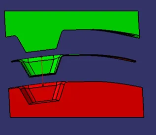
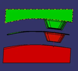
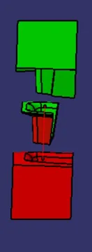
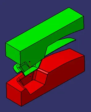
Step -4: - After creating the new geometrical set and name as core design and use the rectangular sketch to extrude until the core required height. And trim the surface with the parting line. After that fill the surface and join the trim part and fill the surface it will form a close surface and the fill material. For the insert the new part file and use close surface. so that the core surface will form.
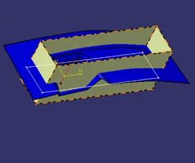
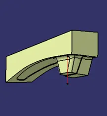
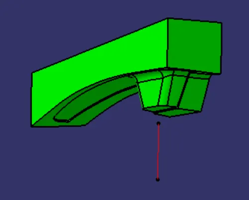
Core & cavity: - Every mold was divided into two parts 1.Core 2. Cavity
- The core is the part with contains the impression of the mold or on the other side we can also call male part of the mold 2.cavity depressions of the mold or we can call as the female part of the mold
Step -5: - the next step is to create the cavity surface and repeat steps use the rec sketch and extrude it and trim with the parting surface and fill the opening of the surface by fill command and insert a part file and name as cavity and use the fill surface command in the part workbench and select the joined surface and select ok the part file is formed.
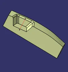
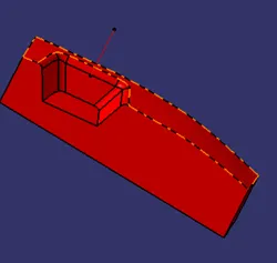
Step -6: - next step starts with creating the parting line for that use the intercept command and select the trimmed A & C surfaces and B-surface the parting line is formed.
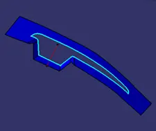
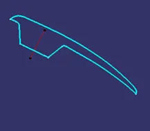
Parting line:- parting line and parting surface is having the same feature but in the parting line parting surface is also included
Step -7: - After creating the part file use the Draft analysis command of the part using the same Tooling Axis for the Draft analysis. To Assess the draft analysis command, go to Insert Analysis Feature Draft Analysis. Draft analysis interface will open and use compose option and select the UCS and fix the axis to the component. And check the draft position correct or not if it is in the wrong direction change to inverse the draft direction. If any changes are required for the changes in the walls Draft angle adjust the sketch to get the perfect Draft angle. Hence the final part was completed with solid features and Draft analysis. Draft analysis is the same for the surface part and plastic component.
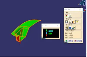
Images of the Core & cavity for the switch bezel mold