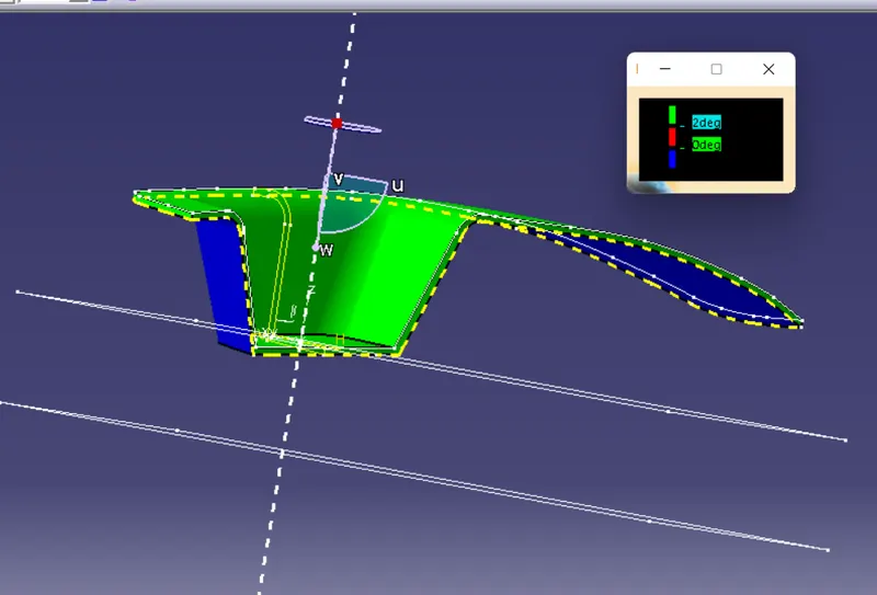
Week 8 - Challenge 5 - Core & Cavity Design
Core and cavity design for a switch bezel:
Objectives:
a) Create core and cavity block of switch bezel body.
b) Create parting line and parting surface.
c) Performing draft analysis on switch bezel.
Core and cavity block:
In the process of injection molding, there will be a core and a cavity block present where the molten material is flown in the gap.
The block that has an outer projection is considered as core block, while the one that has a depression in it is considered a cavity block.
For the switch bezel the core and cavity blocks are considered in the following places shown.
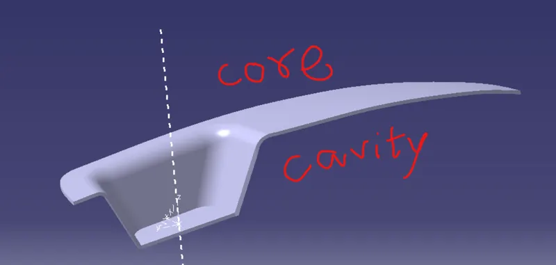
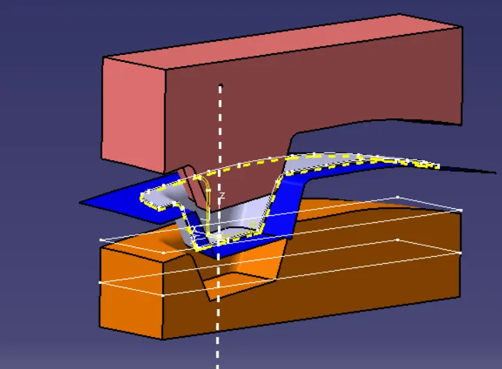
The parting surface lies at the interface of core and cavity block. The parting line is the intersection of parting surface with class-B surface.
Creating a parting surface:
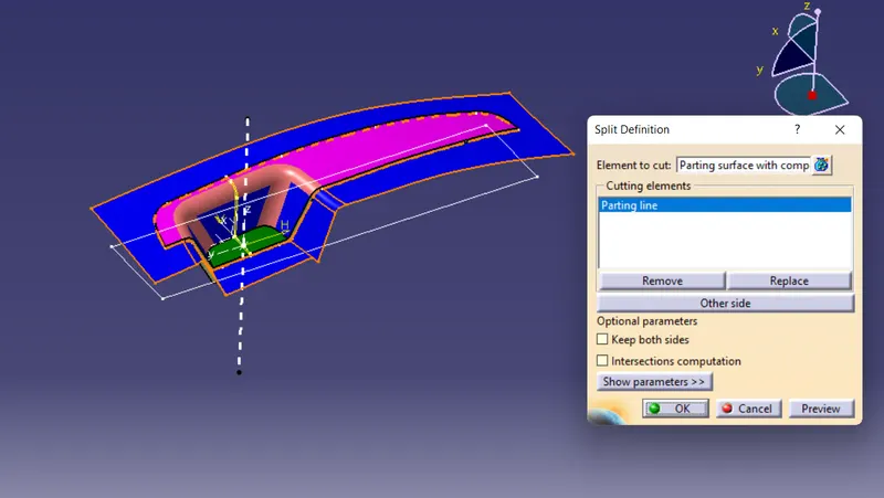
To create a parting surface we need to first create a parting line. The A-surface of the bezel is extrapolated with its outer boundary. It is then trimmed with C-surface. This trim is intersected with B-surface to form a parting line.
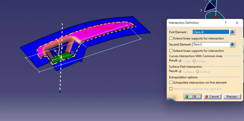
The trimmed surface of A and C is again trimmed with B -surface. This surface is split with parting line to form a parting surface.
Core design:
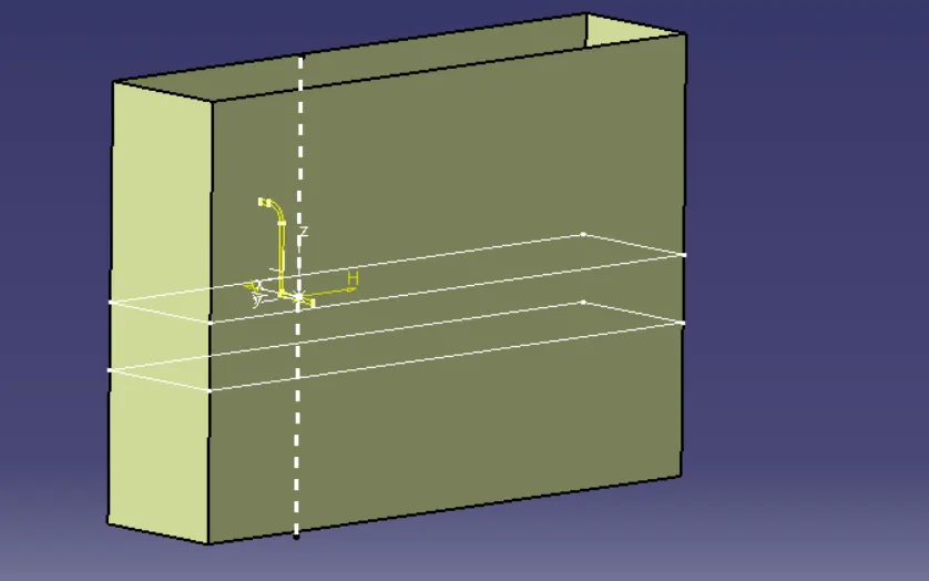
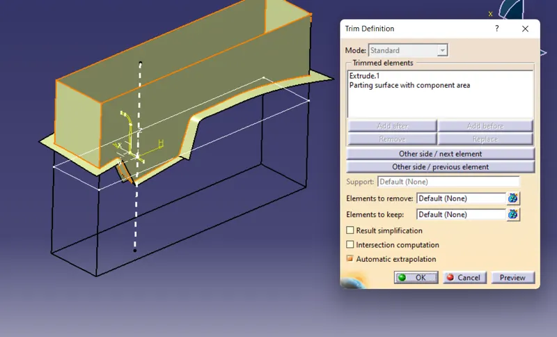
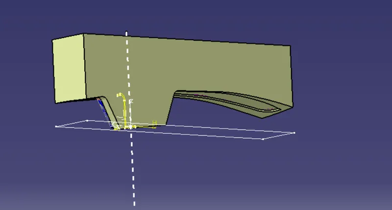
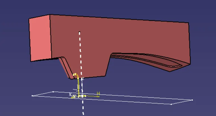
A point is created in the middle portion of depression. With this point as origin an axis system is formed. With the axis system, a rectangular sketch is created as shown below. It is extruded to the required limit and trimmed with parting surface. This forms the closed surface of core. Solid object is formed with closed surface command.
Cavity design:
The same rectangular sketch used for core is extruded in opposite direction. Vacant portions are filled through fill surface command. The resultant surface is trimmed with parting surface to form closed surface of cavity. The solid object is formed with closed surface command.
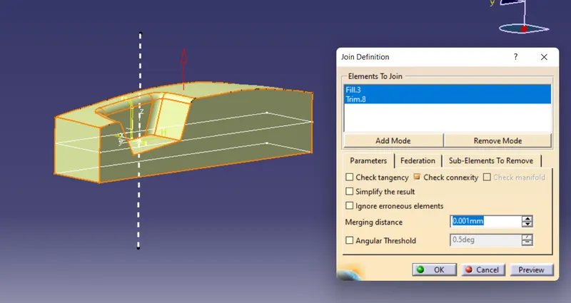
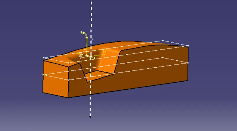
To clearly show the core, parting surface, solid object, cavity.
Tooling axis:
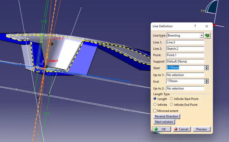
The tooling axis is created using bisecting method. The Z-Y and Z-X planes of axis system are intersected with A-surface. A line with bisecting method is created with two line in Z-Y plane. This is tooling in Y-direction.
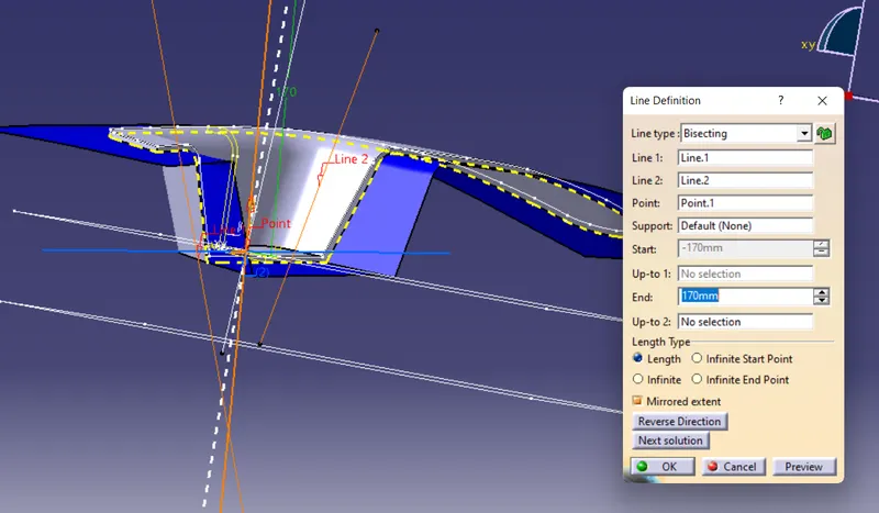
Another line is drawn in Z-X direction at an angle of 6 degrees with the side wall. This is tooling in X-direction.
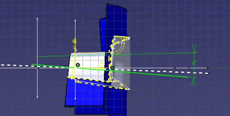
The main tooling axis is created by bisecting these two tooling axes.
Draft analysis :
Draft analysis is done with the following steps:
a) Select the materials option in View customization toolbar.
b) Select "Feature draft analysis" in "Analysis" option.
c) Select the compass button in draft analysis box and orient it in tooling axis direction.
d) Lock the direction of compass and click anywhere on the surface to get complete draft analysis.
Draft analysis of Class-A surface:
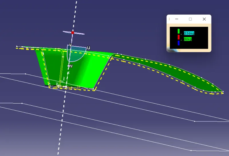
Draft analysis of Solid object: