Week 8 - Challenge 5 - Core & Cavity Design
Core & Cavity Design (Challenge-5)
What is Generative Shape Design?
The Generative Shape Design provides an extensive set of tools for creating and modifying mechanical surfaces used in the design of complex shapes or hybrid parts, its feature-based approach offers a productive and intuitive design environment to capture and reuse design methodologies and specifications. It helps to design advanced shapes that are based on a combination of wireframe and extensive multiple surfaces which includes high-level features with full specification capture and reuse.
What is Draft Analysis?
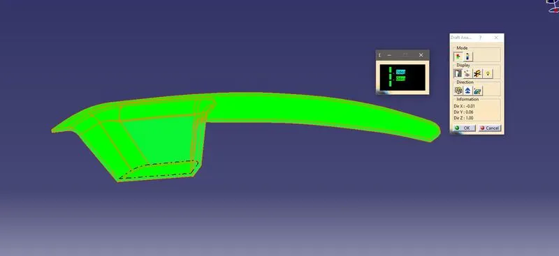
The Draft Analysis command enables you to detect if the part of you drafted will be easily removed, this type of analysis is performed based on color images identifying zones on the analyzed element where the deviation from the draft direction at any point corresponds to specified values.
No parts can be ejected from the tool if it is having a straight 90-degree profile from its base surface, a small draft angle is provided to each and every area of the component in order to get an easy removal of the component from the tool. Draft analysis technique is used to analyze whether our part model created in cad is manufacturable based on the draft condition applied.
In the molding process the molded parts have to eject from the die so there are some issues while removing the molded parts it may get sticky with the die, or while removing the chances to get damaged, so we need to set up is the draft angle this draft angle helps the molded part to eject from the die easily.
What is Parting Line?
A parting line, in industrial casting of molds, is the border line in which draft angles change direction. That is, it is the dividing line that splits the core and cavity halves of molded part. It is sometimes a starting point for the mold parting surface. In engineering drawing, parting line is often abbreviated as PL. ASME’s Y14.8 Standard specifies a symbol for the parting line.
What is Parting Surface?
The parting surface of a mold are those surfaces of both mold’s plates adjacent to the impression which butt together to form a seal and prevent the loss of plastics material from the impression.
What is Core and Cavity?
The core & cavity are the shaped sections in either half of the mold tool which gives the plastic product its final shape. The hot molten material is injected into the core & cavity and then sets hard into shape. The design of the core & cavity is essential in the correct formation of the product
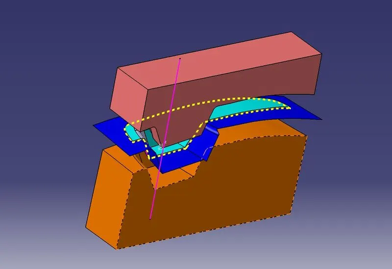
Design Methodology
Parting Surface
- Extract the Class A surface boundary lines with boundary option.
- Extrapolate the Class A surface by 15mm.
- Trim the extrapolated surface with Class C & B surfaces respectively.
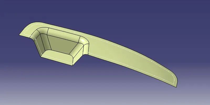
Design Core
- Open the new sketch in XY plane.
- Create a rectangle and constraints it.
- Extrude the sketch on both sides.
- Trim the parting surface with the above surface of the rectangle.
- Fill the open surface with the Fill
- Join the filled surfaces with the trimmed surface.
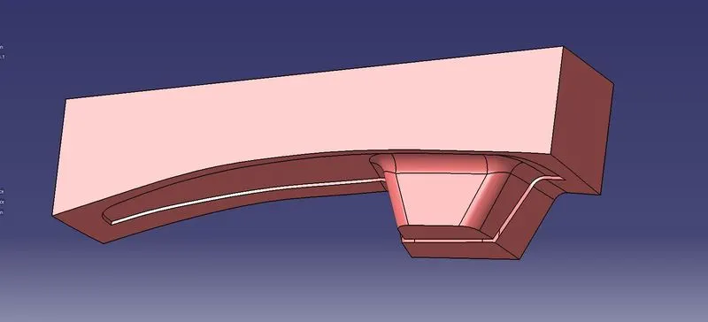
Design Cavity
- Trim the extrude surface with B surface.
- Fill the open surface with the Fill option.
- Join the Filled surface with the trimmed surface.
- Now open the Part Body.
- Create two bodies separately and create closed surfaces.
- Intersect with the perpendicular plane and unhide the tooling axis.
- Translate the bodies in required directions.
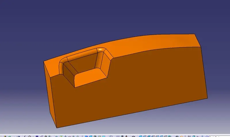
Draft Analysis
- Go to the Insert Menu and select the Analytics option.
- Select the feature Draft Analysis.
- Select the Material Option and select the surface.
- Drag the compass and place on tooling axis.
- Make sure that the top surface is in green color as the draft angle should not exceed 3 Degree.
- Click on OKAY after confirming the model
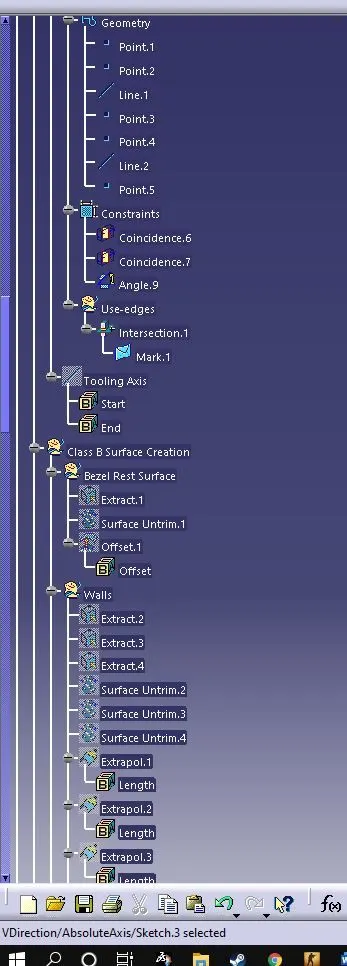
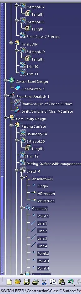
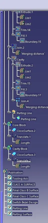
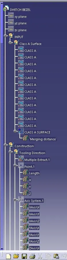
TREE