Week 8 - Challenge 5 - Core & Cavity Design
Objective: To create core and cavity for the switch bezel along the direction of tooling axis using Cata V5R21 with engineering standards.
Procedure For Switch Bezel:
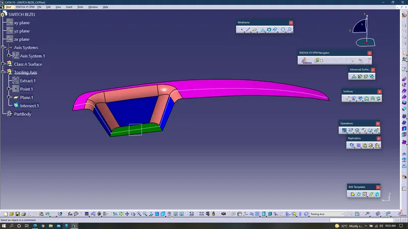
1. Obtain Class A surface from styling team and perform connectivity check using boundary command.
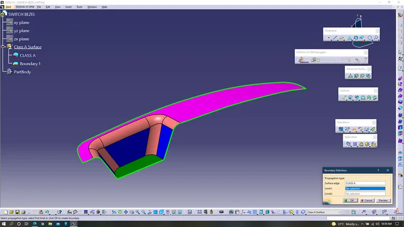
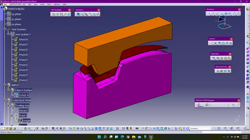
2. To perform draft analysis for the given class A surface, tooling axis must be created. Tooling axis can be created by extracting the surface and creating a point over it.
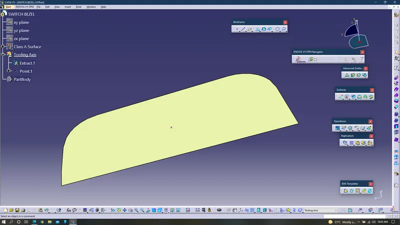
3. Create an Axis system at that point.
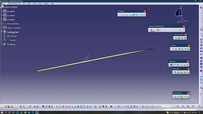
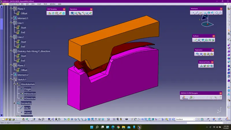
4. Create a plane with reference to the YZ axis.
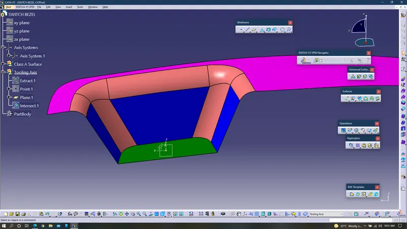
5. Use intersection curve command and select all the surfaces and select the plane to obtain intersection curve along Y-direction.
6. Extend the lines of the intersection curve using point to point line command and next create a bisecting line by selecting those extended lines and point.
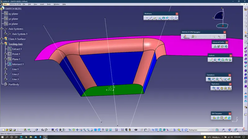
7. Rename the line obtained from the bisecting line and create another plane along ZX axis.
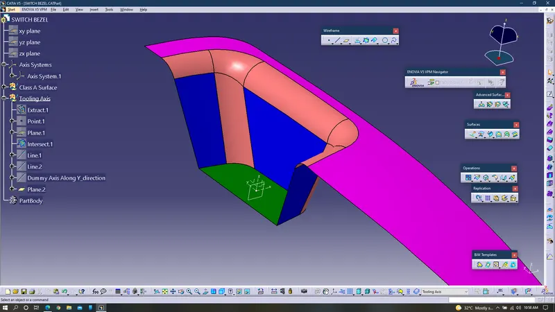
8. Use intersection curve and create the intersection curve along X axis.
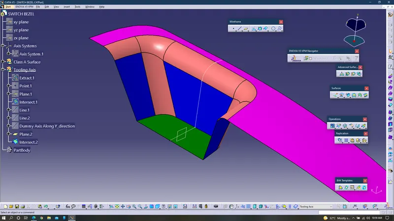
9. To obtain dummy tooling axis along X-direction, a sketch must be created along the plane ZX.
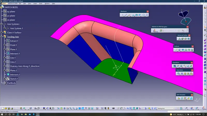
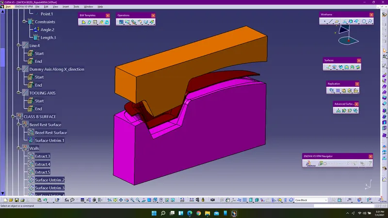
10. Use bisecting line and obtain the dummy axis along X-driection.
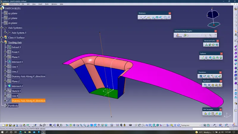
11. By selecting the both dummy axis along x&y directions create a bisecting line at the point and rename the line as the Tooling Axis.
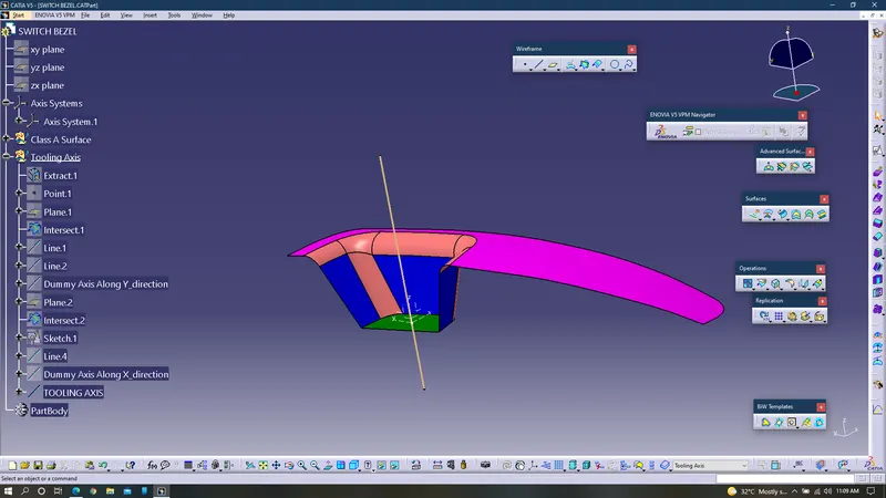
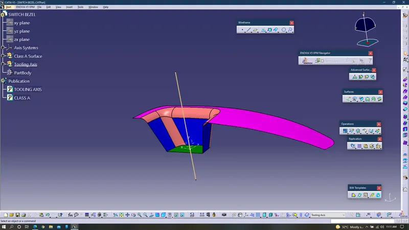
12. For easy reference publish the class A surface and tooling axis(line).
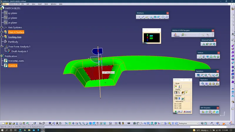
13. Perform fetaure draft analysis for class A surface. It is clear that one of the surface does not have the minimum angle required for manufacturing, which can seen in red colour. Since it is a class A surface designers donot have permission to edit it, so this surface is called for verification by the styling team. If in case it is not possible to edit by the styling team too then we have to change the angle accordingly so later part we will be changing the angle between the line along ZX axis and surface to 9.5deg to compensate the draft analysis.
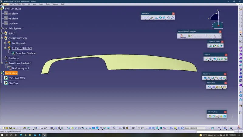
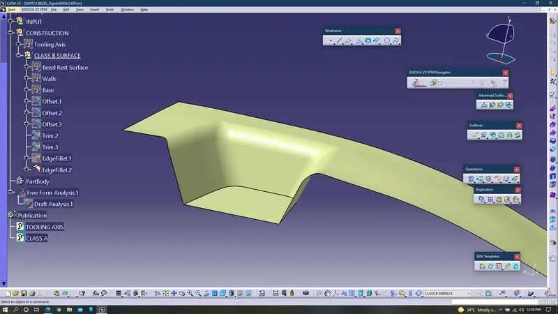
14. For creating class B surface extract base of the switch bezel.
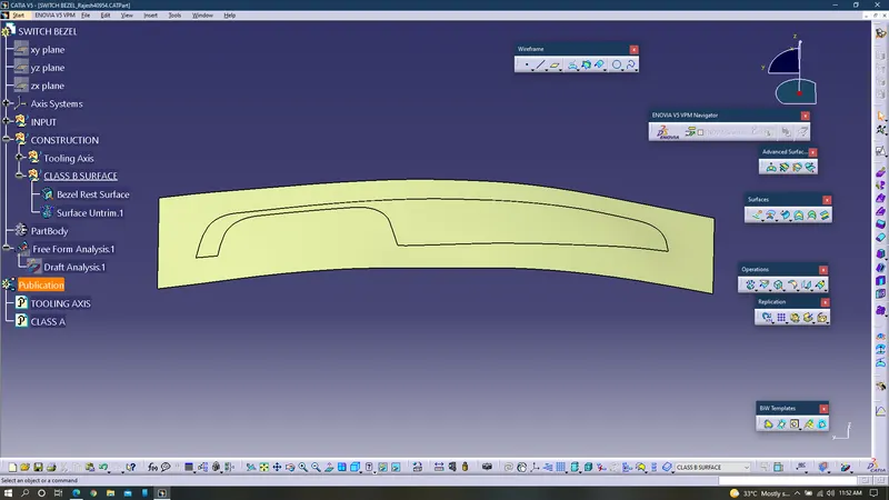
15. Untrim the extracted surface.
16. Extract the walls of the switch bezel in the new geometrical set and name it as walls.
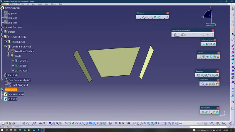
17. Untrim the exrtacted walls of the switch bezel and extrapolate them.
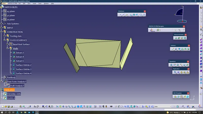
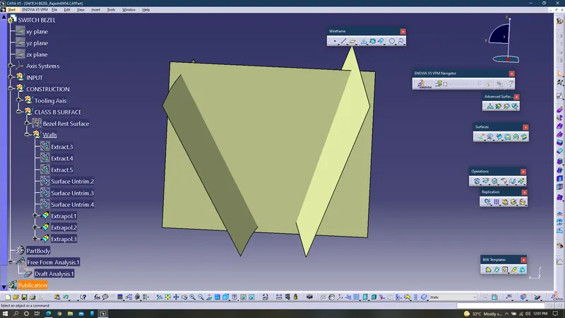
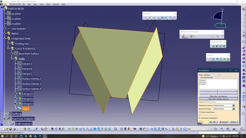
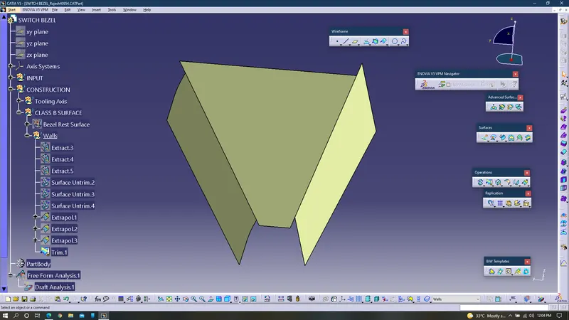
18. Trim the extrapolated surfaces.
19. Extract the base of the switch bezel in the new geometrical set which is named as base.
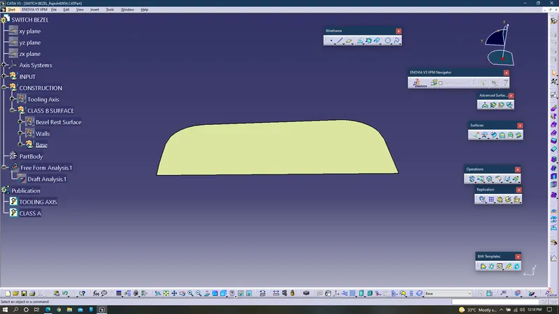
20. Untrim it and extrapolate the base extract.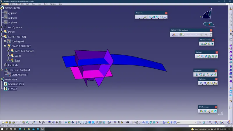
21. Offset all the surfaces with a distance of 2.5mm.
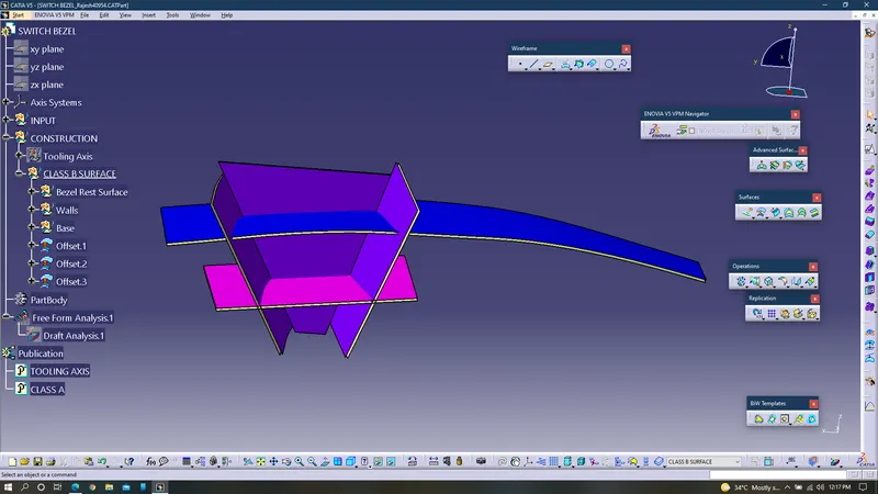
22. Trim the surfaces to the required shape.
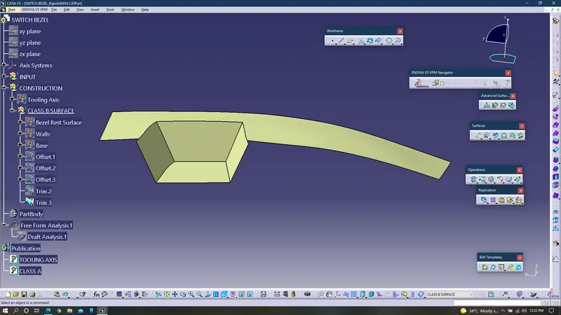
23. Apply fillets to the surfaces.
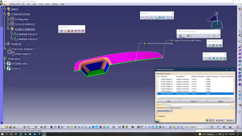
24. With the help of multiple extract, extract the edges of the class A surface.
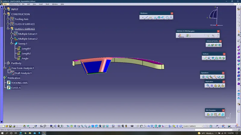
25. Use sweep command and select the draft direction as tooling axis and create class C surface.
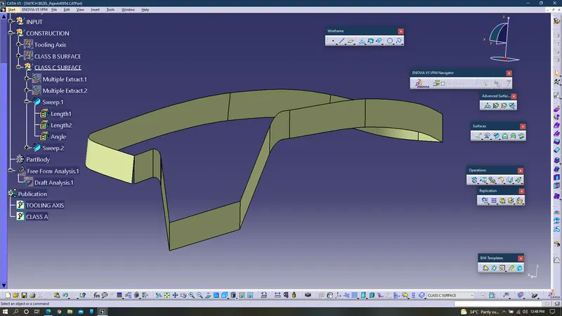
26. To remove those small patches which makes difficulties while manufacturing use the smooth curve for the both multiple extracts and replace them with the newly created smooth curves.
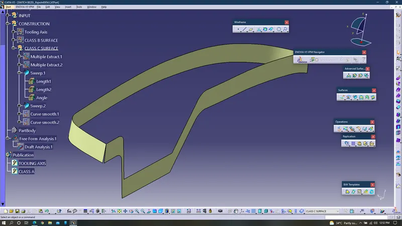
27. To remove the gaps between the surfaces, extrapolate them and trim the surfaces for providing a closure between them.
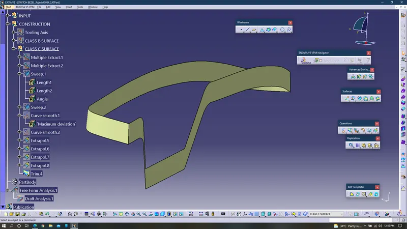
28. Join the class A & C surface and perform a boundary check.
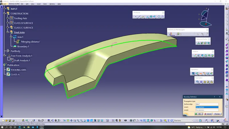
29. Trim the class B surface, by selecting join and B surface using trim command.
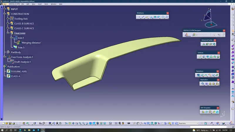
30. Enter into part design module and use close surface command to convert the surfaces into solids.
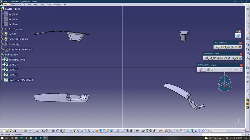
31. Perform feature draft analysis for the whole component.
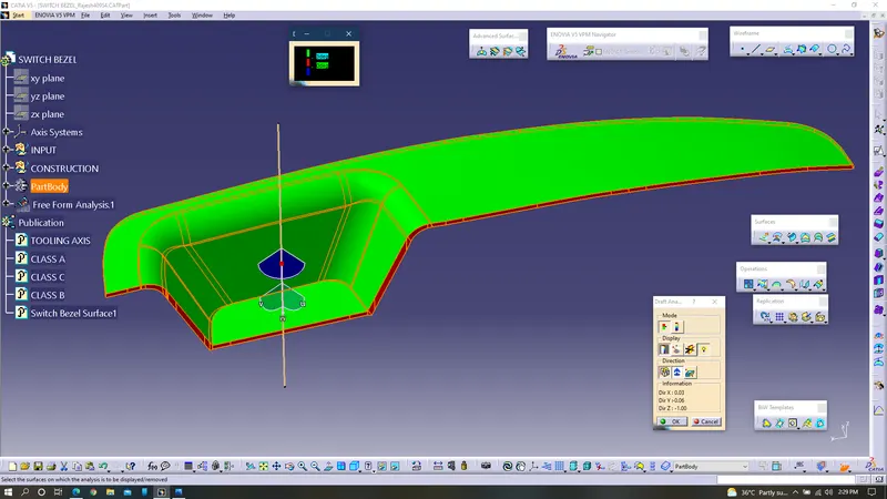
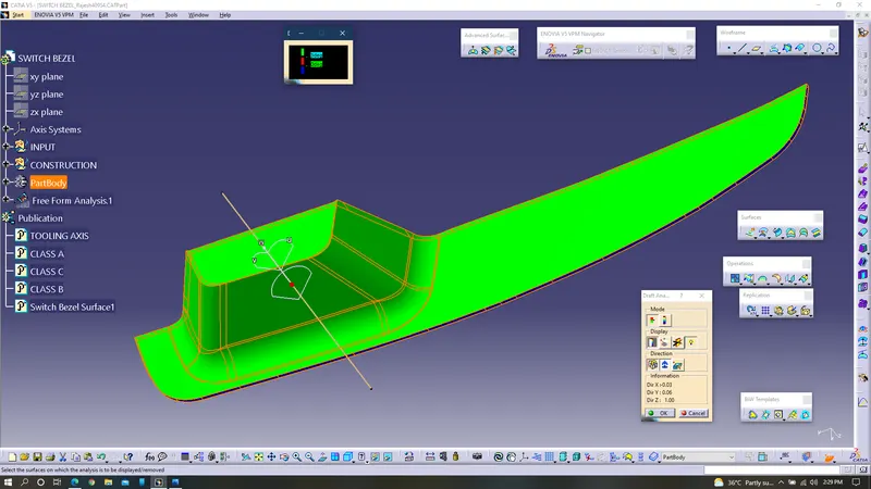
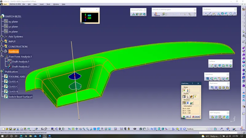
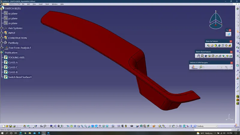
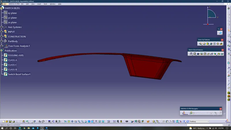
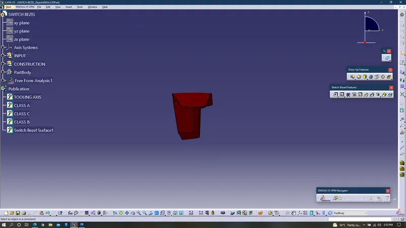
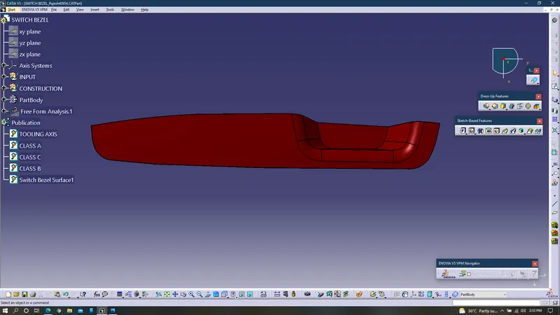
Views of switch bezel:
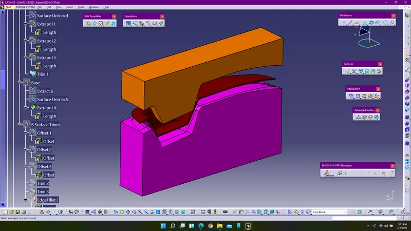
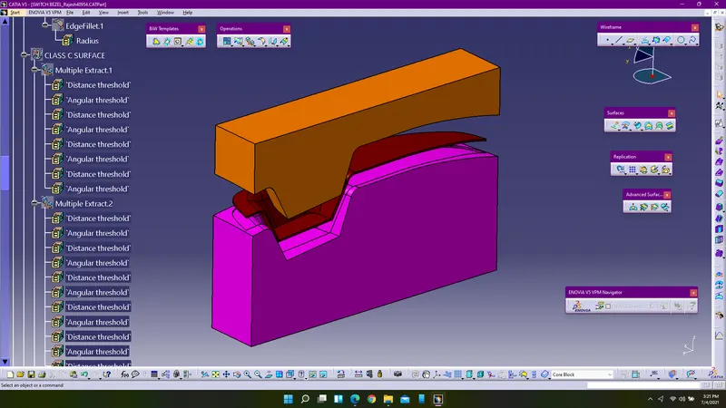
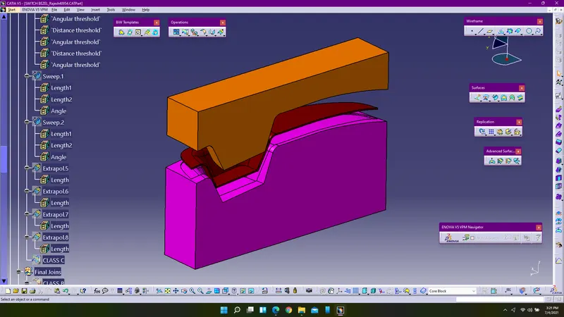
Feature Tree Diagram of Switch Bezel:
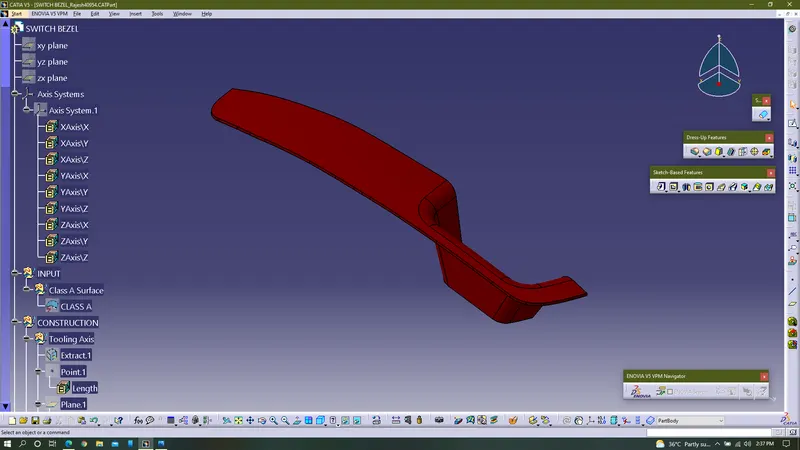
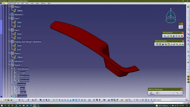
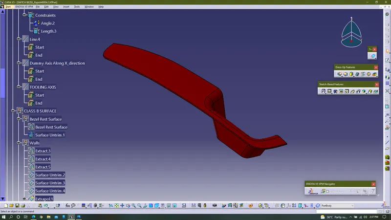
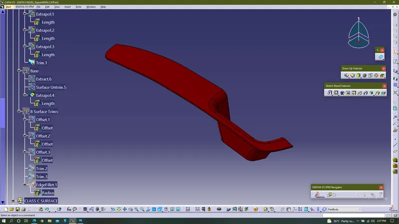
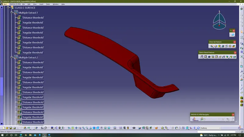
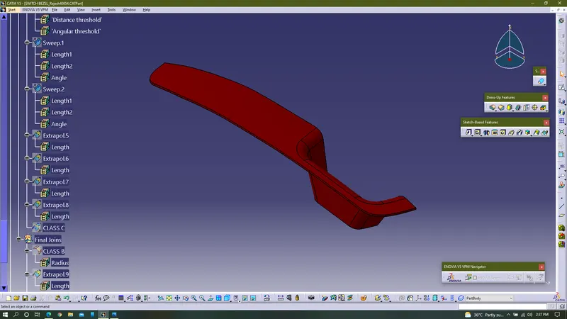
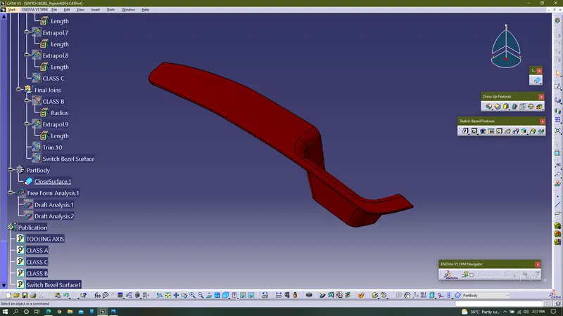
Procedure For Core & Cavity Design For Switch Bezel:
1. Switch bezel which has been created in the previous challenge is obtained and used for creating core and cavity, previously draft analysis is also performed on the switch bezel.
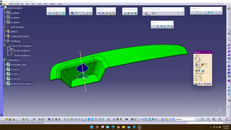
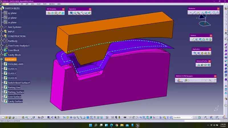
2. Create parting line by extracting the boundary of the class A surface and change the graphical properties of the parting line and rename the boundary as parting line, for our convience publish it in the publication.
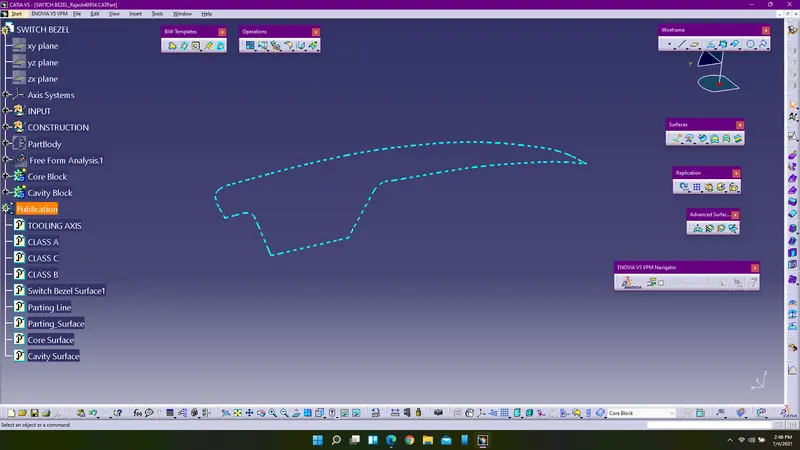
3. Next step is to create parting surface for core and cavity, to create it extract the surface of class A and extrapolate it. Rename the extrapolated surface and name it as parting surface and publish it.
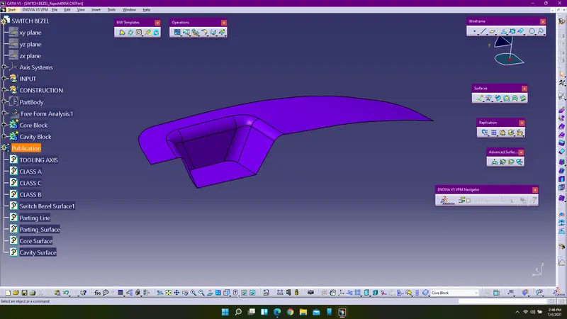
4. Design core block surface by extracting the class A surface and create a sketch-block in the xy plane, extrude the block with along the tooling axis direction and trim the extrapolated class A surface with the core block using trim command. Join all the surfaces and enter into part design and using close surface command convert the surfaces into solids.
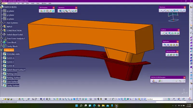
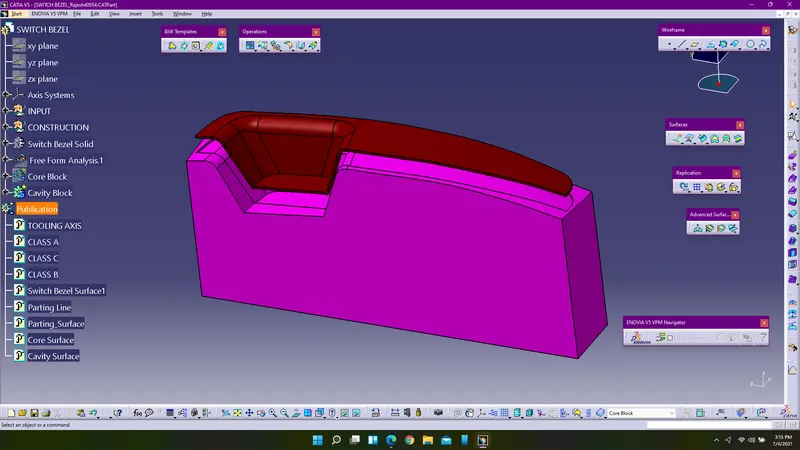
5. Create the cavity block by extracting the C and B surfaces and using the same block-sketch extrude the surfaces and extrapolate the b surface and trim the excess surfaces using trim and obtain cavity surface. Join all the surfaces and enter into part design workbench and using close surfaces convert the surfaces into solids.
Images of Core & Cavity along with the parting line & surface:
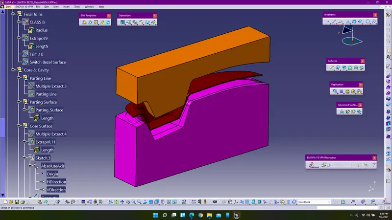
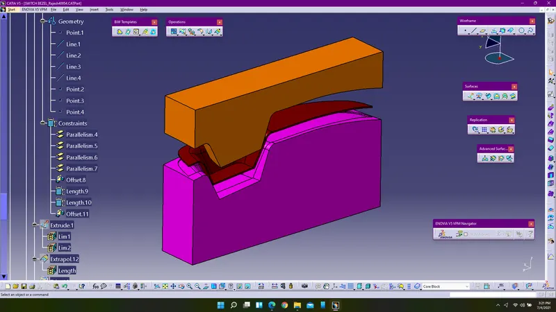
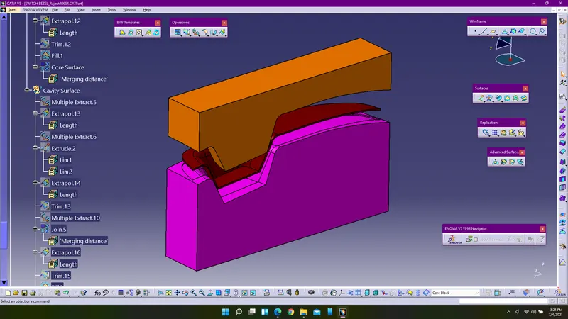
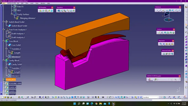
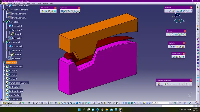
Feature Tree Diagram Of Core & Cavity Of Switch Bezel:
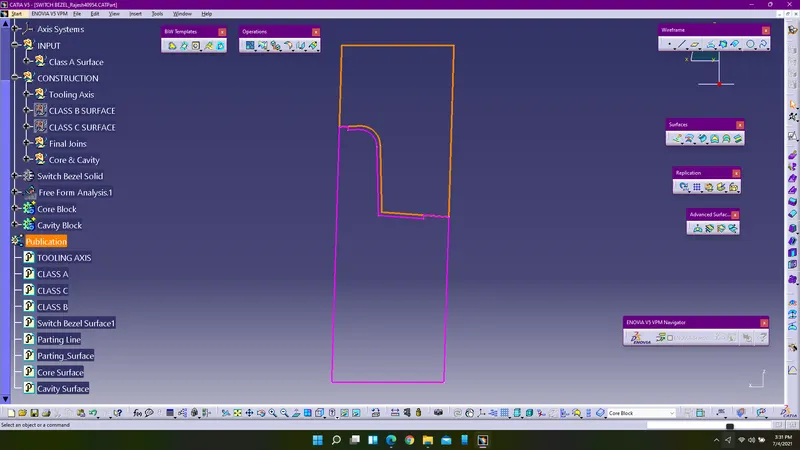
Intersection Curves:
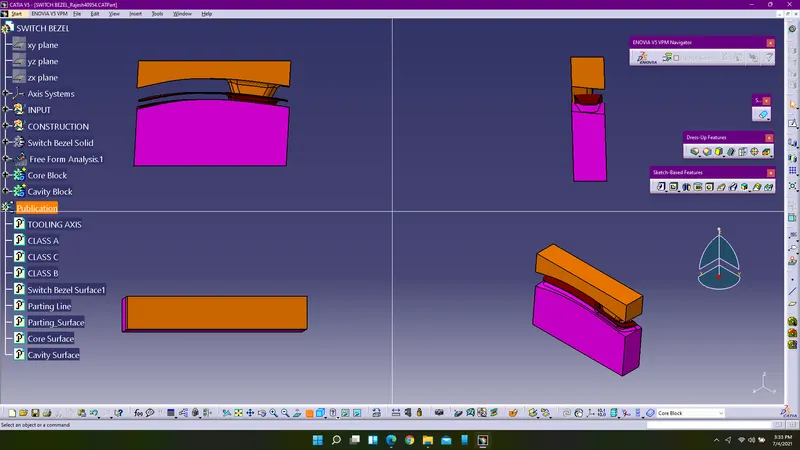
Views Of Core & Cavity:
Conclusion:
Core & Cavity for the switch bezel is designed along the tooling axis and parting line & surface is also created using Catia V5R21.