Week 8 - Challenge 5 - Core & Cavity Design
Core & Cavity Design for Switch Bezel
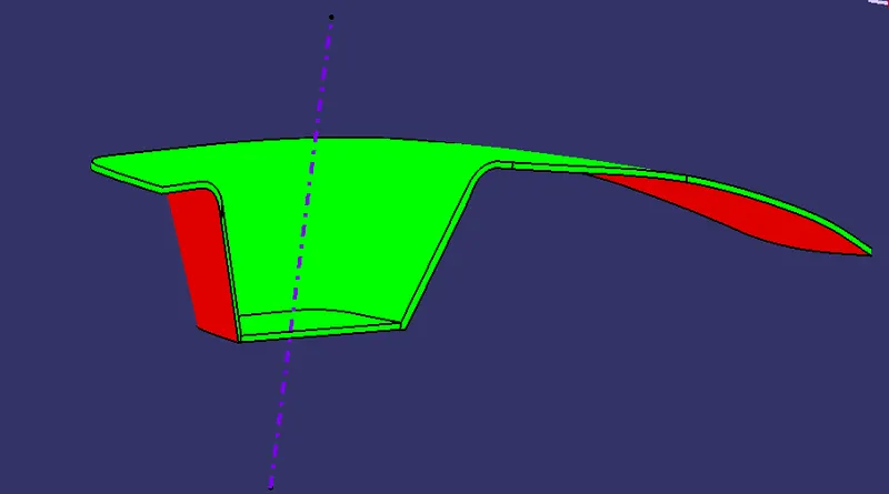
The Draft analysis of the switch bezel is shown below. The green highlighted part have a draft angle of 3 deg and red have negative draft. Here the highlighted green area is the core section and the negative draft section will be the cavity of the mould. The draft analysis assist in selection of core and cavity section of the body with the help of colour coding.
Parting Surface
The first step in core design is to extrapolate the class a surface to a distance of 11mm.
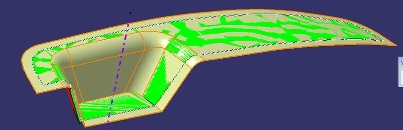
A Boundary is created from the class a and then class c and b surfaces are trimmed with each other to form the Parting surface with the component.
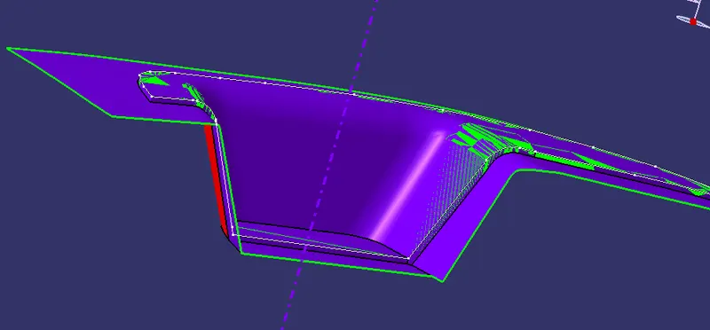
The part body can be trimmed with the above surface to obtain the parting surface
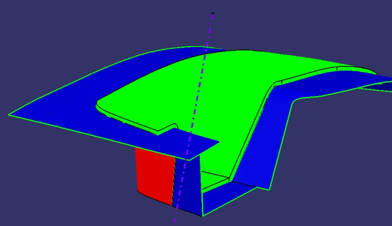
While creating the parting surface it is important to create the surface from class b. following this would improve the product quality and improves the design of the mould and also the moulding process would be easier. Basically the parting surface is the pressed surface between the two halves of core and cavity, it prevents leakage of molten plastic outside the mold. Parting surface is where the core meets the cavity, and usually is located at the largest section of a product. If the parting surface is inappropriately selected, mold structure becomes complex, making it difficult to mold the plastic product, thus affecting product quality. Therefore, the selection of the parting surface is of great importance to the design of mold structure.
Core Design
A Sketch is made on the parting surface surface, the sketch is made such that it is within the parting surface.
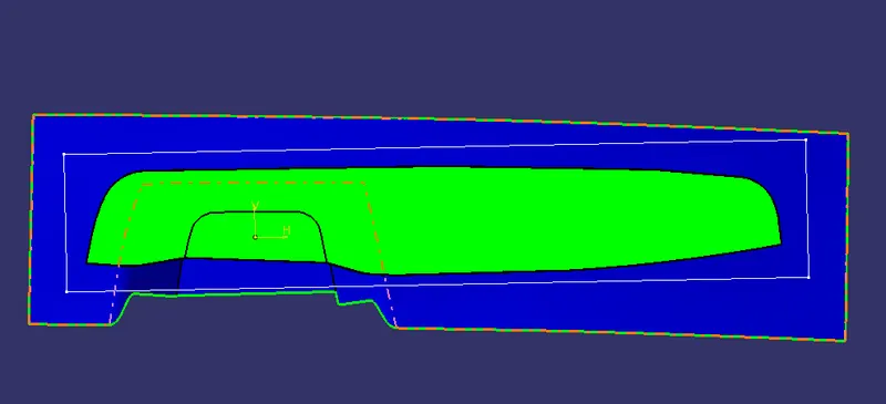
After the sketch is created the sketch is extruded in the z direction on both ends with repect to the tooling axis.
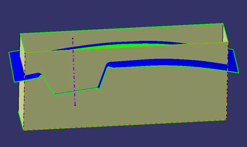
After extrude process the surface is trimmed with the parting surface and the open ends are closed and joined to obtain the core surface.
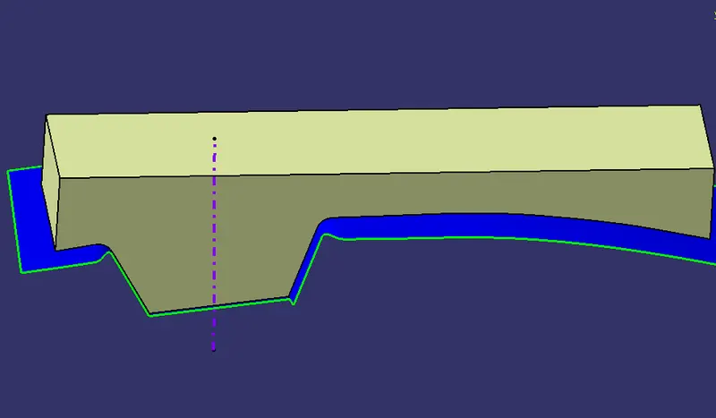
Once the core surface is created part design is selected and using close surface tool the core body is created.
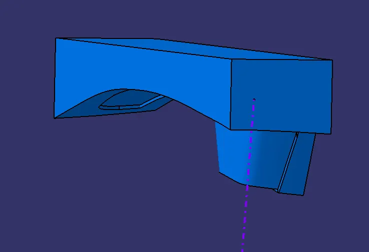
Cavity Design
Intersection is created with the core, parting surface and part.
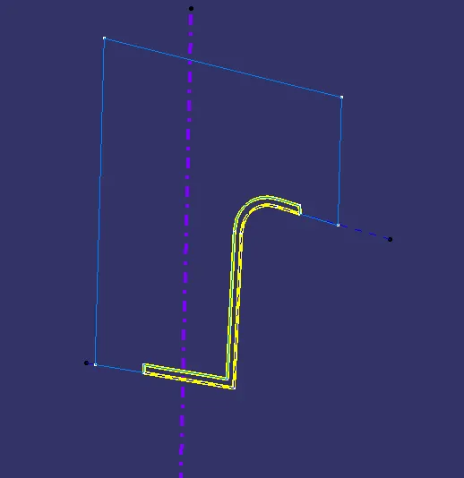
The Core Inersection is extruded with respect to the tooling axis.
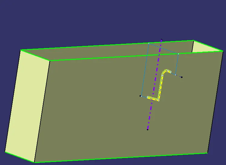
Once the extrude is created the surface is trimmed with parting surface
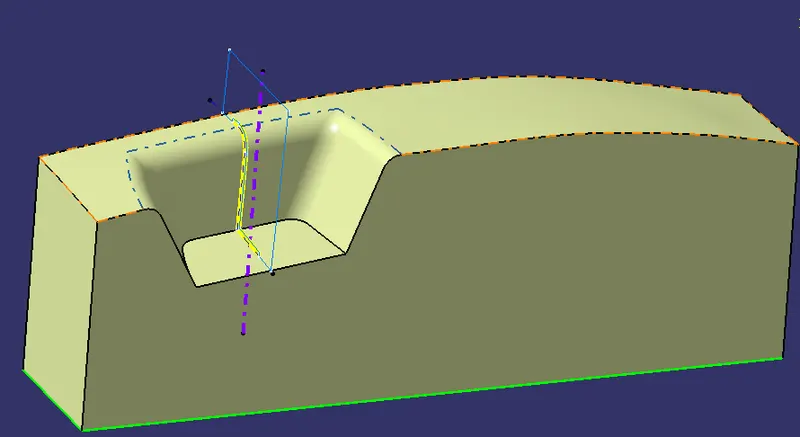
Once the core surface is created and closed part body is created.
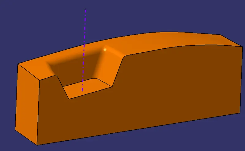
Parting Line:
An Intersection is created using the Parting surface and class C to create the parting line.
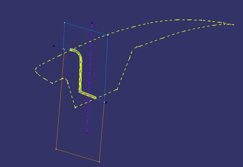
Parting line is the border line in which draft angles change direction. That is, it is the dividing line that splits the core and cavity halves of a molded part. It is sometimes a starting point for the mold parting surface.
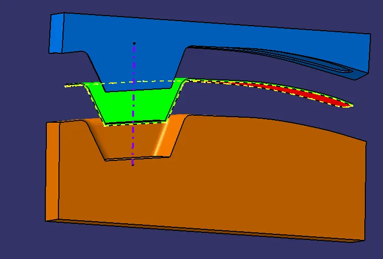
Once the parting line is created Pert Design is selected and using the translate tool the core and cavity is translated 50mm with respect to the tooling axis.