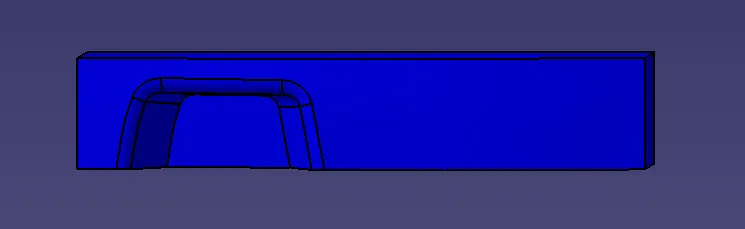
Week 8 - Challenge 5 - Core & Cavity Design
Aim: To perform Draft analysis and create Core and cavity for the switch bezel
Procedure: First we have to make Draft analysis for the given class A surface. To make draft analysis we have to create a tooling axis.
Steps to create tooling axis.
- First we have to select the toolong direction. By analysing the given surface we could observe that Z is the required toolong direction.
- After selecting tooling direction to create tooling axis bisectors of the below blu surfaces should be taken as these are the surfaces which will be difficult to create in this direction.
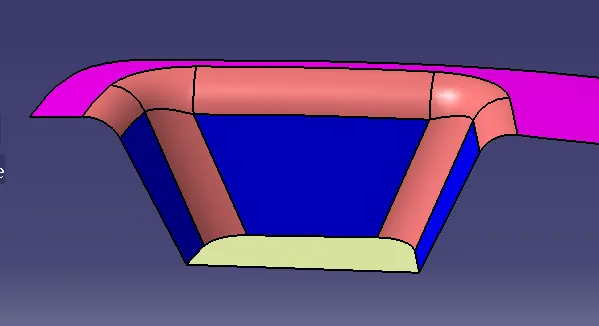
- We will create geometric axis on tha base surface and create a sketch in yz plane. In tha sketch create an intercetion between class C and YZ plane as shown below.
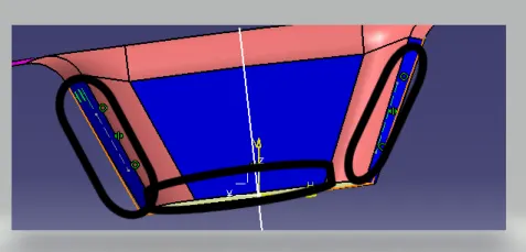
- After creating the intersection we should create the bisection line to get the y axis clearance as shown below.
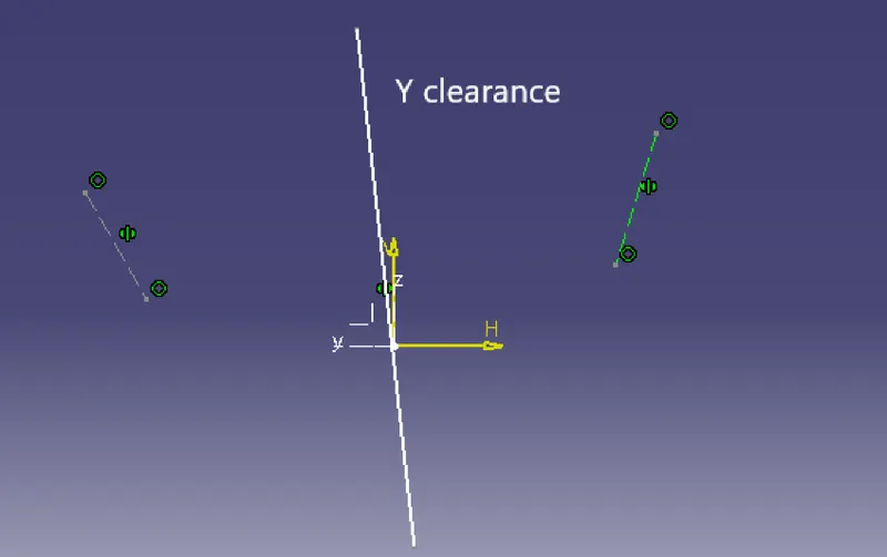
- After getting y clearance now we have to create X clearance axis. To get X clearance we should create a sketch in XZ plane. After creating sketch create an intrection between Class A and ZX plane.
- After creaing intersection we have to create a line from origine at an angle of more than 3 degrees (should not be below 3 as the minimum draft angle is 3 degrees) from the intersection line as shown below which is X clearance axis.
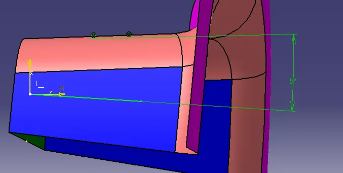
- Now after getting the 2 clearances from X and y axis now we have to create a bisection line between these two to get the tooling axis.
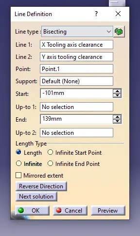
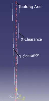
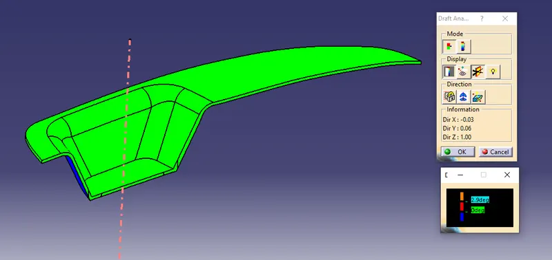
- After getting the tooling axis we have to perfome draft analysis. To perform draft analysis the view should always in Material mode.Now select the draft analysis feature. keep the compass on the tooling axis and then selet the class A surface.
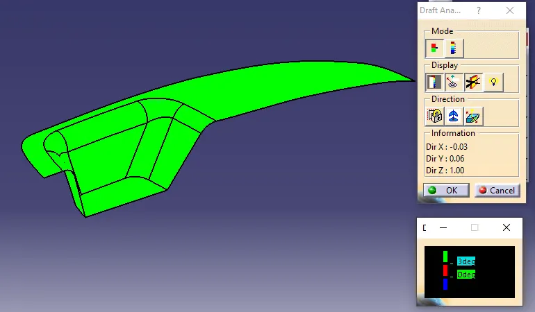
- The below colou code shows that the surfaces below 0 as blue, surfaces between 0-3 as red and above 3 as green. The reason for giving 3 is the minimum draft angle we consider is 3.
- Hence we got green for the class A it is clear that we can manufacture the surrface so we can proceed for creating class B.
- While creating class B class C the draft should be outside i.e +ve draft should be taken. The reasson for taking +ve draft is creation of flashes.
Flash: Flashing is caused by leakage of material caused during moulding. It is removed by cutting.
- Hence the flashes are removed bu typical cutting process he marks will be remained so the if draft is given in +ve direction it cannot be seen in class A which makes model looks good.
- After creating the class B and C surfaces we should create a solid body by using fill surface command.
- Once the solid body is created we should conduct the draft analysis for the solid part to check the draft angles and weather the part can be manufactured or not.
- As we have geen for the total surface we can conclude that the part passed the draft analysis and can be manufactured.
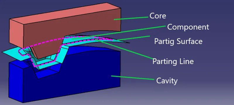
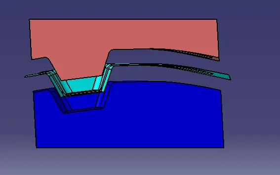
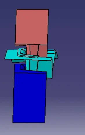
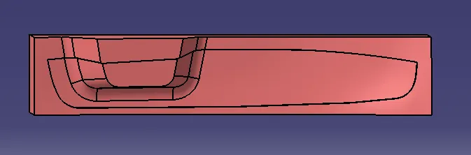
As we have performed drat analysis now we can design Core and Cavity for the Switch bezel. To create core and cavity first we have to create parting surface.
Parting surface: It is a surface which saperates core and cavity. It is one of the important considertion for mould design.
Parting Line: It is the intersection line between parting surface and the component.
The parting surface should always be on Class B because the flashes are formed in parting surface so if it was in class a surface then to remove flashes we swill use hand cutting which won't give perfect cutting. hence parting surface should be in the class b