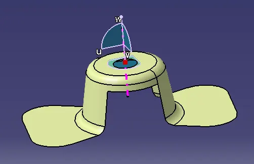
Week 8 - Challenge 1 - Draft Analysis on a Fan Cover
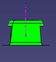
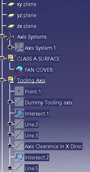
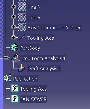
Steps requed to perform Draft analysis
- The first step while performing draft analysis is to check the continuty of the class A. We should ensure that there are no gaps.
- The second step is to create the tooling axis which is the most important part in draft analysis.
Following are the measures to be taking for creating tooling axis
- Firast we should select the appropriate tooling direction by checking in all the 3 directions.
- The appropriate tooling direction for the fan cover is z because of the following reasons
1. If the tooling direction is in Y direction we should require the side core to make hole on the to which increases the cost. So it is not the appropriate tooling direction.
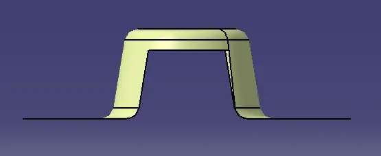
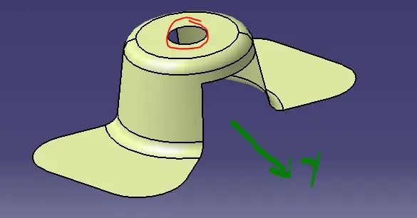
2.If the tooling direction is in X direction we should require the side core to make hole on and also for the slot at the side which increases the cost. So it is also not an appropriate tooling direction.
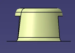
3.If the tooling direction is in Y direction then we can produce the hole, side cavity and all the remaining surfaces. So it is the suatible tooling direction.
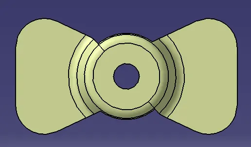
- After selecting the tooling axis we have to check weather all the surfaces can be produced through that direction. Follow are the steps to check it.
1.First we have to create a referance(Dummy) tooling axis in Z direction.
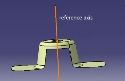
2.After that we have to create an intercets for the surfaces in X and Y directions to get a tooling axis.
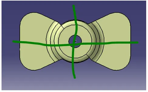
- By considering surfaces in X direction we could locate that the below two surfaces may cause difficult in producing.
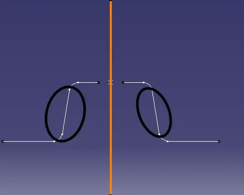
- So we should check the possibility by creating an intersection line in the direction of tooling axis. To create an intersection line first we have to create two line in the surface direction as shown below.
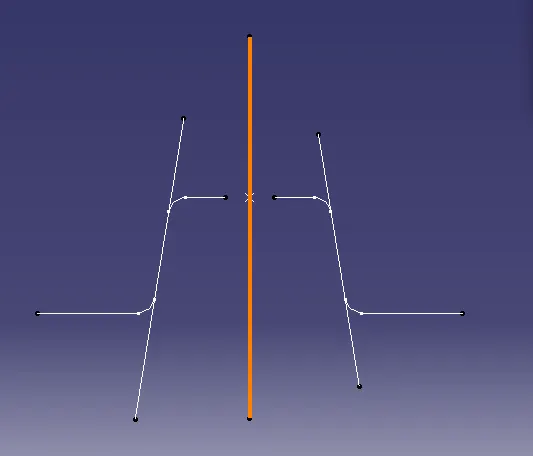
- Now we will create an Bisection line for these two lines to get the axis clerance in X direction(Show in below figure)
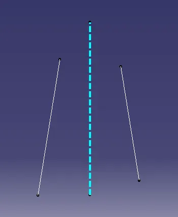
- Now by considering surfaces in Y direction could locate that the below two surfaces may cause difficult in producing.
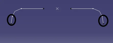
- So we should check the possibility by creating an intersection line in the direction of tooling axis. To create an intersection line first we have to create two line in the surface direction as shown below.
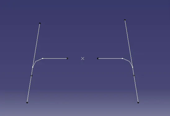
- Now we will create Bisection line for these two lines to get the axis clerance in Y direction(Show in below figure)
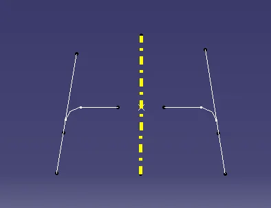
- After getting both the clearance axis we will generate a tooling axis by bisecting both the clerance axis.
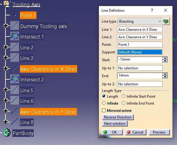
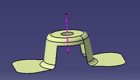
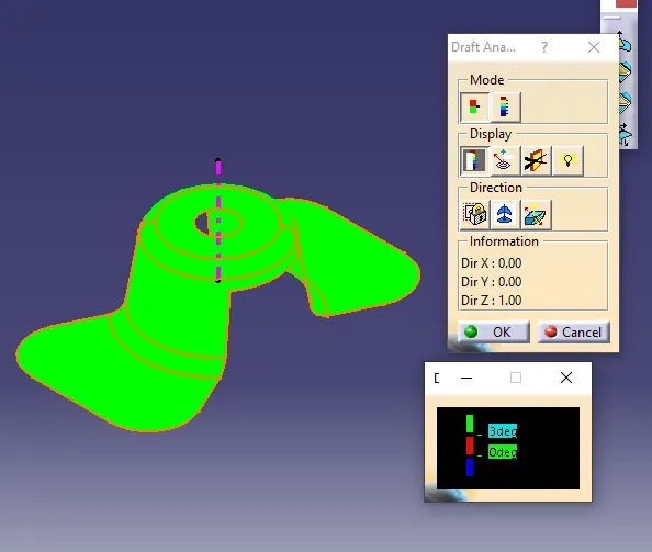
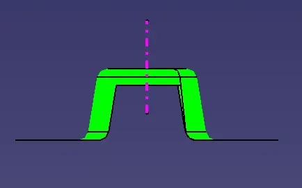
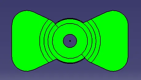
- After creating tha tooling axis we can make draft analysis by selecting deature draft analysis. While selecting we should make shure that viwe mode should be in "Material" only.
- After selecting analysis we should give the tooling asix in the compass (shown below) and select the Class A for analysis