Week 8 Challenge
1.Inroduction:-
Centrifugal force is force on bridge due to curvature in alignment of road or track. Load produce by curvature due to moving vehicle on bridge.
Here we calculate the load thrust load due to curvature of live load
2.Aim:-
Here required data are provide and we need calculate load due to centrifugal force due to 70R loading on 2 lane bridge. We calculate the effect due to centrifugal load with the help of staad pro .
3.Data :-
i.Span of Bridge - 12m
ii.Carriage way -7m
iii.Live Loading -70R tracked vehicle
iv.Design Speed of vehicle -75 km/hr
v.Radious of curvature -3m
4.Procedure :-
According to IS Code Load due to Centrifugal force
`c=(wv^2)/(127r`
=`(700*(75)^2)/(127*3)`
=10334.6
~10335 kn/m
Now centrifugal force has been calculated. now need to apply this load with help of staad pro.
1.Open the staad pro and create the model as showing given below pic.
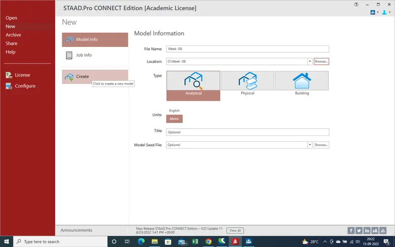
2.As select the "create " a main window has been open to create the model.
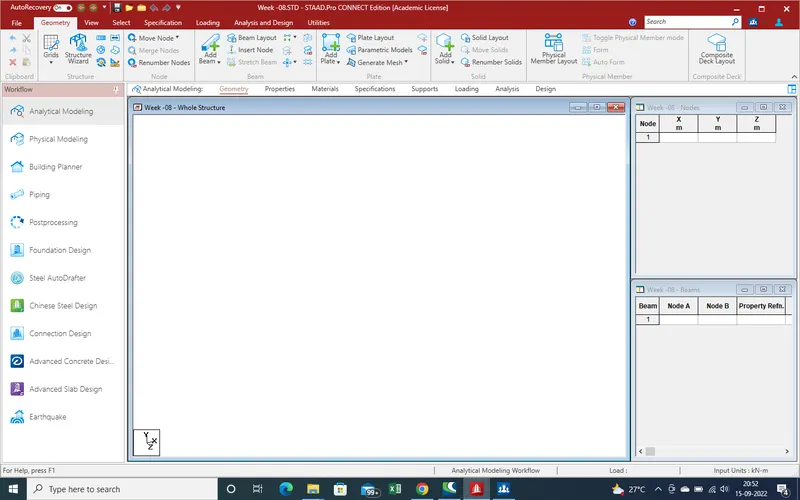
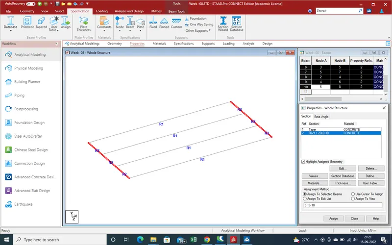
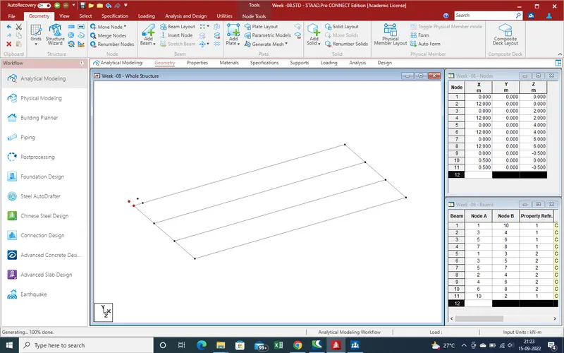
3.Start modeling , as showing model pic is not clear so we assume that there is 4 nos of main girder and 2 nos cross girder with slab thickness of 250mm .
Although girder are fixed at pier cap with the help of pined support so we consider only upto pined support reaction
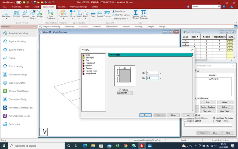
4. Create the main girder which width is 800mm and depth is 1500mm and cross girder are 300mm width and depth is 1200mm
5.As here span is 12mtr so node distance are 12mtr created .
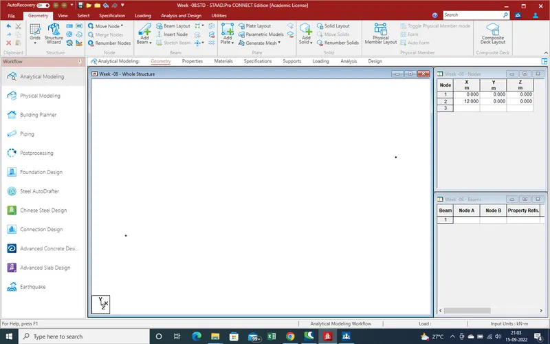
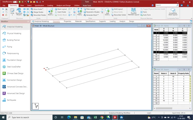
6.Create beam with help of Add Beam Command
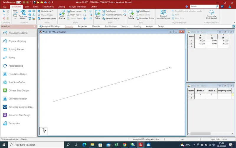
7. With help of translation command create remaining 3 main girder at 2mtr spacing
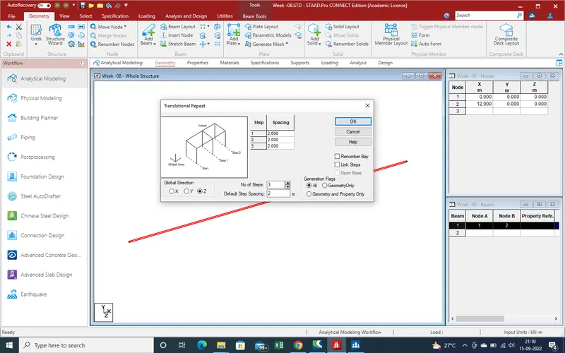
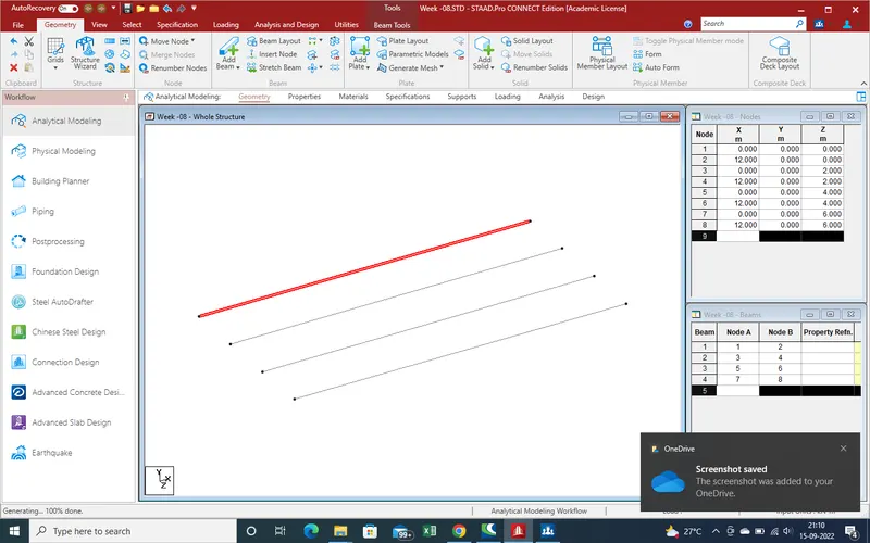
8. Creatr the Property of main Girder and Apply on it
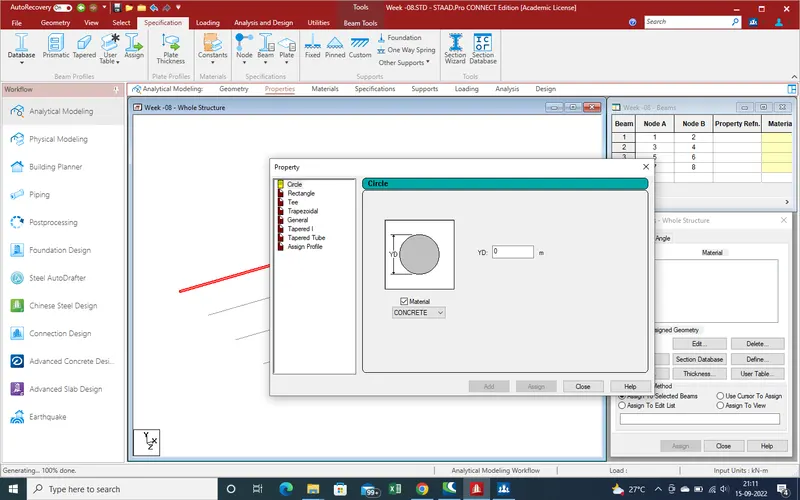
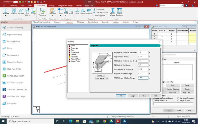
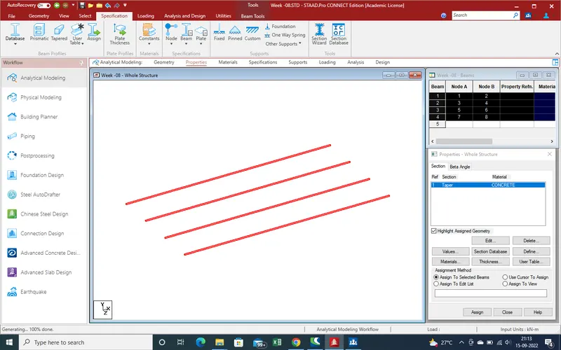
9.Now Create the Cross girder with help of "Add beam " .
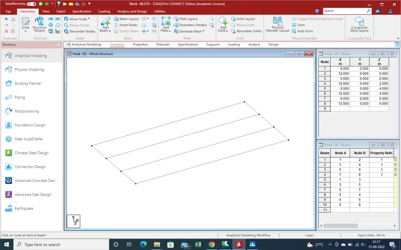
10. Now again create the property and assign
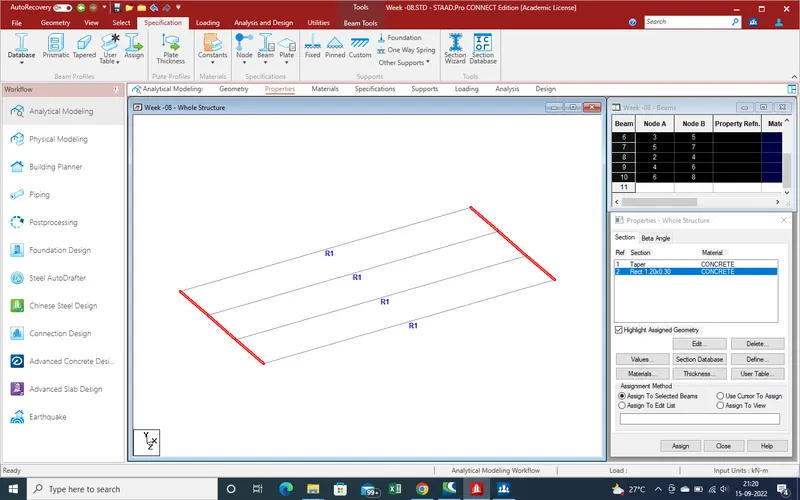
11. Now Create the Slab Over the Span
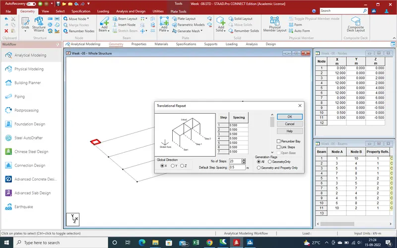
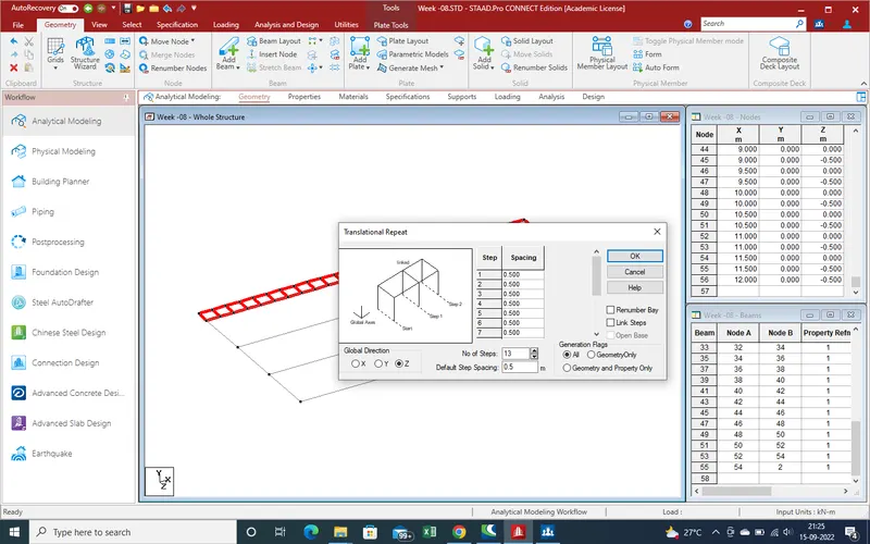
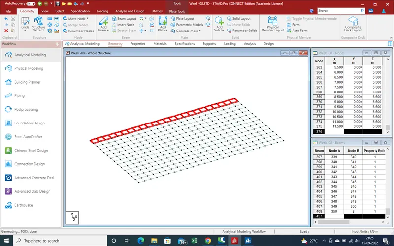
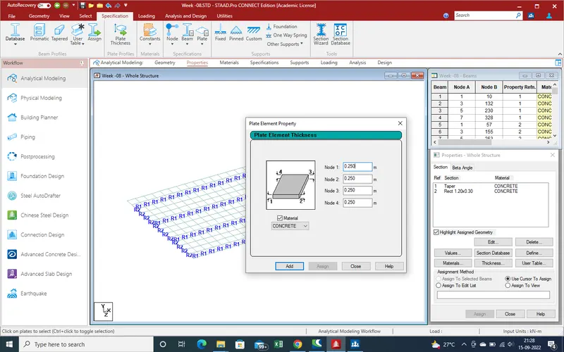
12. Apply the Property of Plate thickness
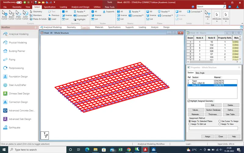
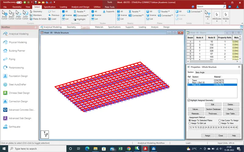
13. Now Assign the support reaction

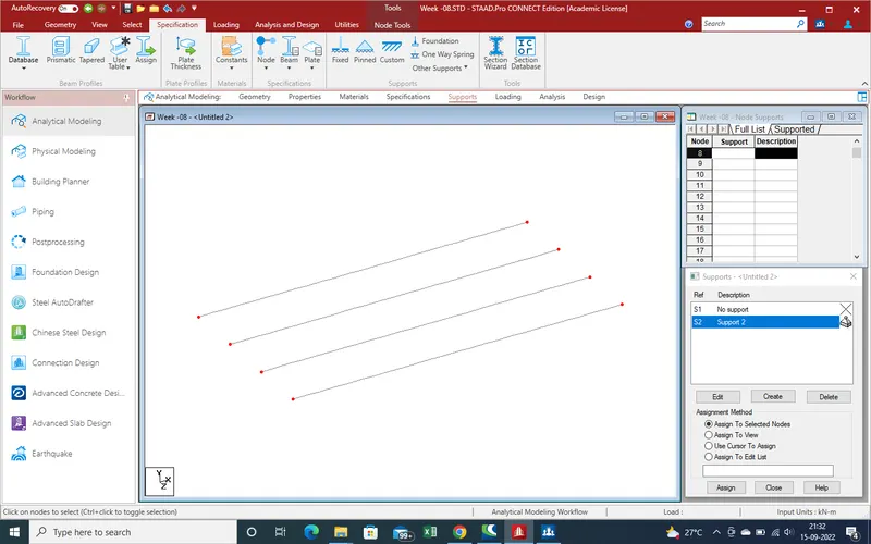
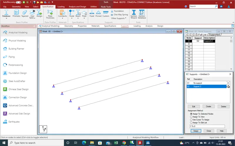
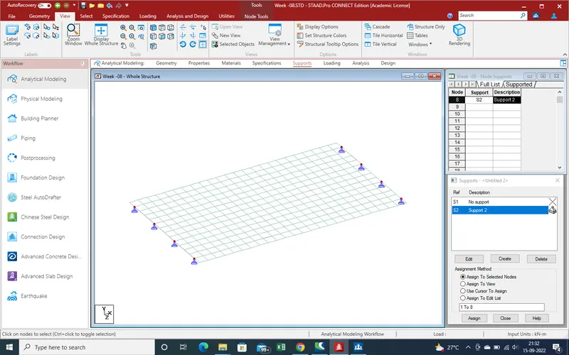
14. Modeling work has been complited , now we define loading and create the load cases and apply
15.Go to loading section
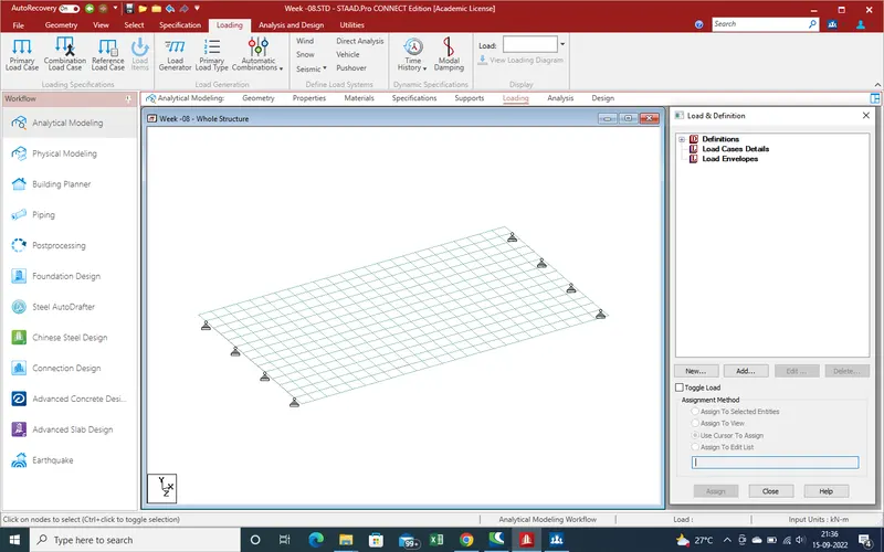
16.Select first of all Defination and select the vehicle defination
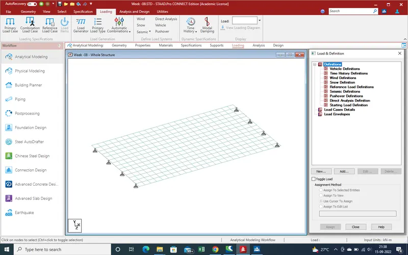
17. Select the vehicle defination and click on "add", a new window open
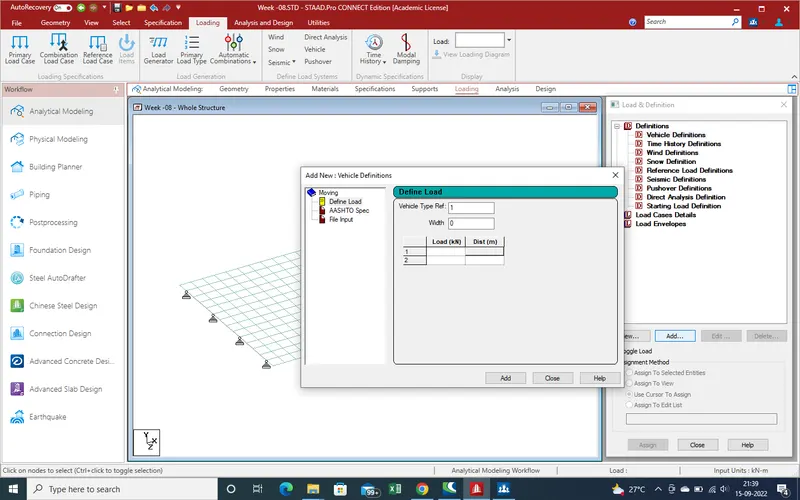
18. As in starting given that loading of live load is 70 R loading so centre to centre distance is 2.060m and loading is as we calculated is 10335 kn/m
now put the values in given load in Vehicle loading
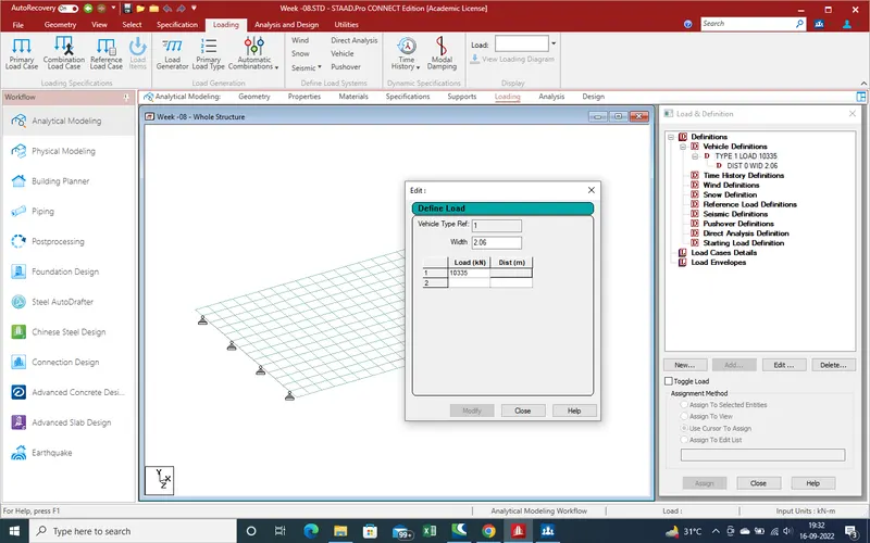
19.Load defination has been defined, now create the load cases
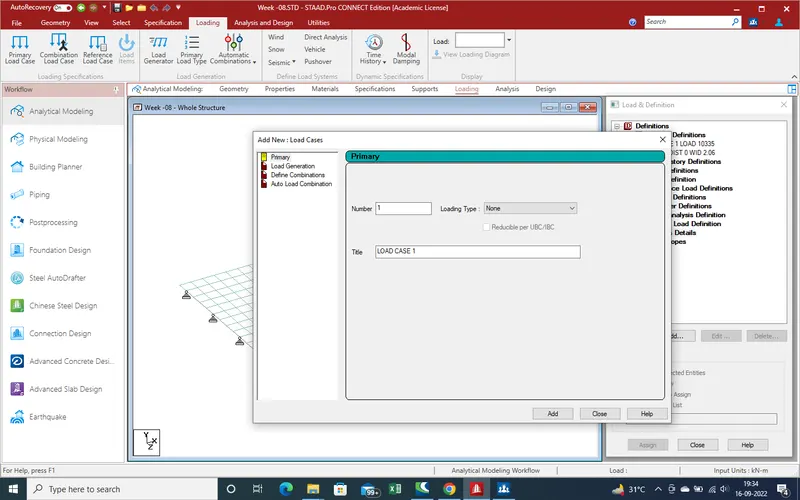
20.Here select the load generation as load is moving load over the slab
As interval of loading is 0.5m so no load assume 24+vehicle length as here asume unit length so 2 can be consider . total no of cases are 26 nos
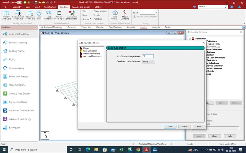
21.Now Again select the load case and select the add for define postion of loading as per irc code
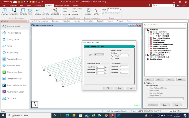
22.As in traced vehicle c values is 1.2 m from kerb edge and and tyre width is 0.840m so centre distance from tyre is 1.2+0.420=1.620m .
Put the value in Z-Direction , X-Direction starting point value and same as for y-Direction
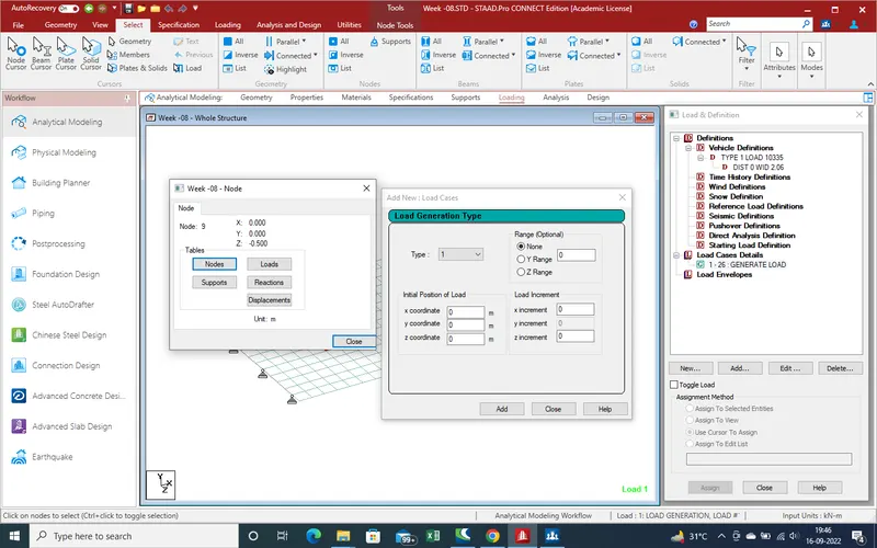
23.As here node value X- 0,Y-0 and Z in negetive 0.5 so value Z is 1.120 m
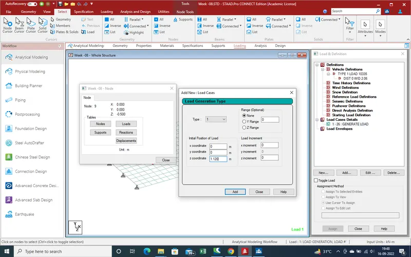
24. As put the value now select the range direction and increment value as 0.5
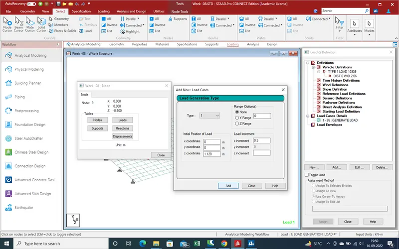
Click on Add and Close the window
25. Now Run the File for get the results
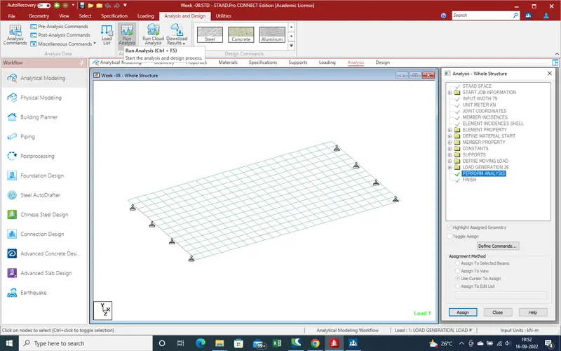
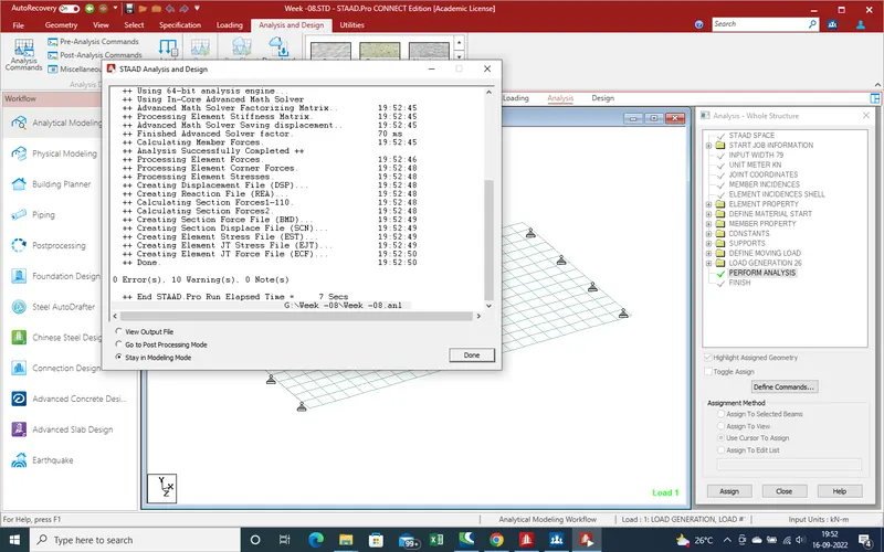
26. There is no error means all are ok . Now we select the Postprocessing mode for get the results
4.Results :-
1.Select the Ok For See the results .
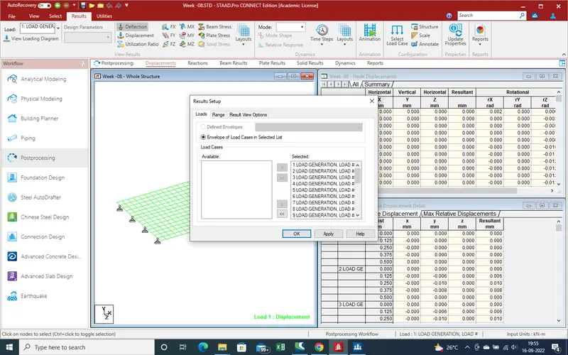
2.Loading as showing on the slab.
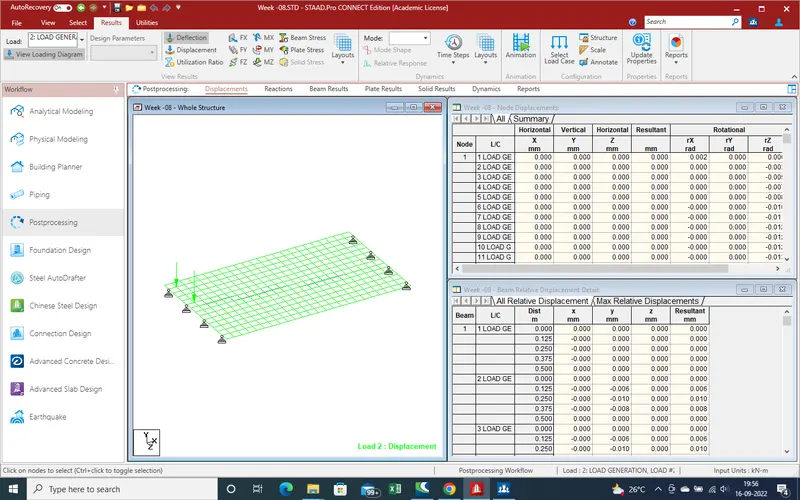
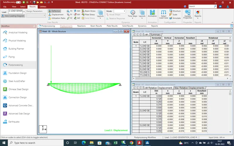
3.Deflection due to Live loading.
4.An Another position deflection due to centrifugal force
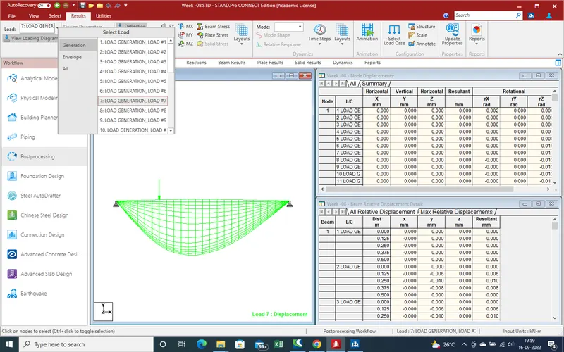
5.Node Displacement due to load .
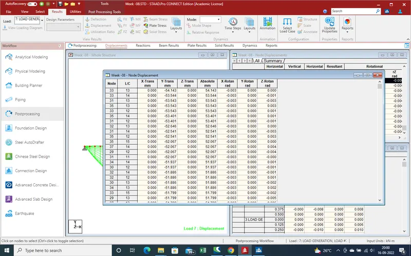
6.Beam Deflection
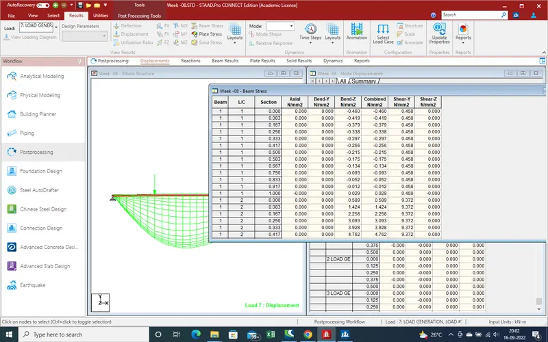
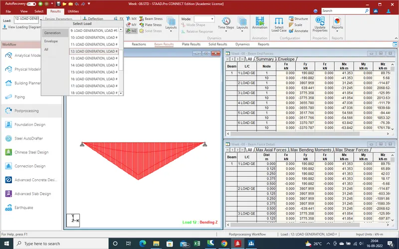
7.Beam results due to load
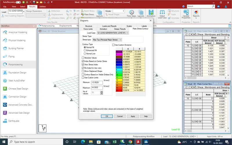
8.Plates results
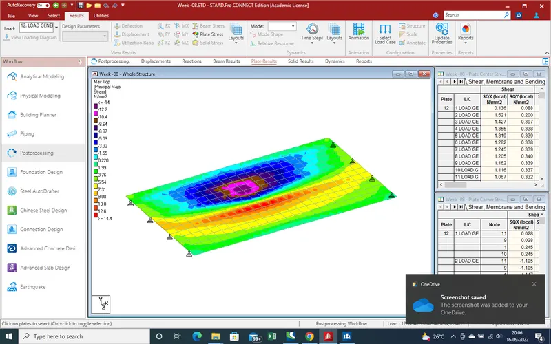
9.Shear deflection
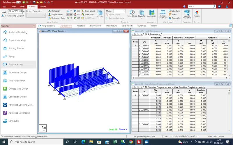
10.Moment About X-Axis
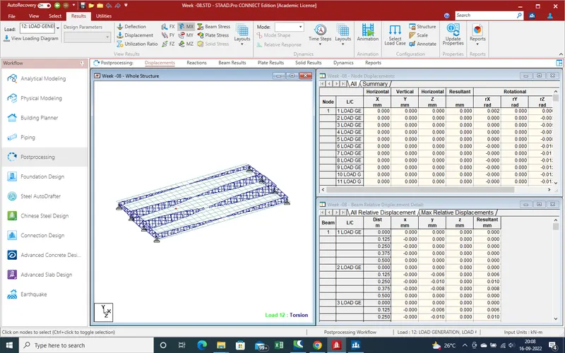
11.Moment about Z-Axis
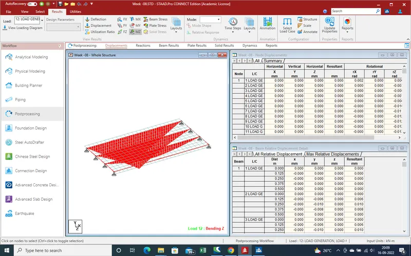
12.Beam Stress
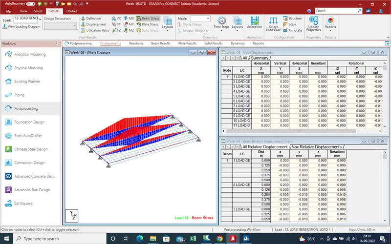
13.We can find out the attached copy for report.Also attach the model file.