Week 8 Challenge
1)
Aim: To apply the load for the structure model in the previous exercise.
- Form a Load case as DL for Dead Load
- Apply Self-weight
- Apply member load of 3 kN/m on the rafter
- Apply member load of 6 kN/m on the secondary beams
- Apply point load of 20 kN at node intersecting inclined member on the top chord.
- Form a Load case as LL for Live Load
- Apply member load of 4 kN/m on the rafter
- Apply member load of 7.5 kN/m on the secondary beams
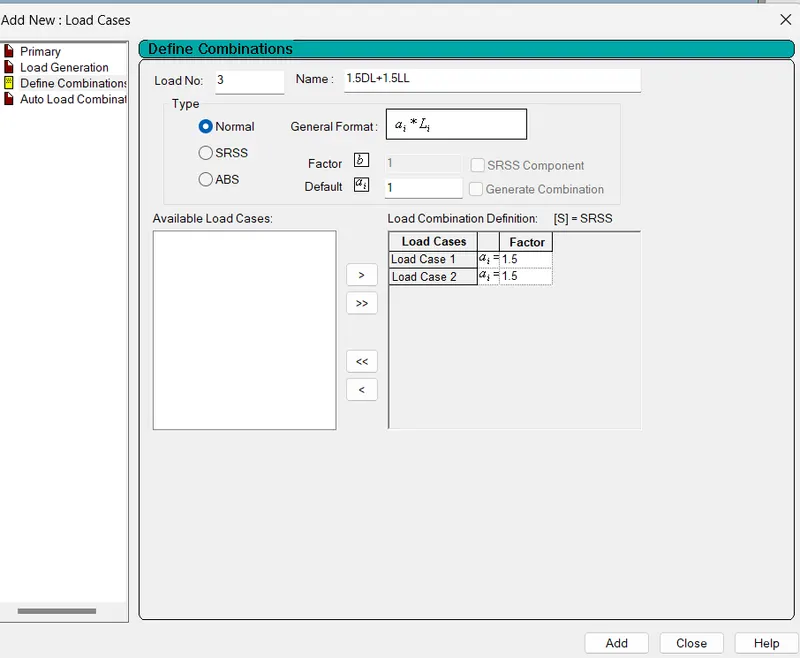
- Form load combination 1.5DL+1.5LL
Procedure:
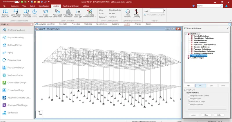
Step 1: Open the STAAD file of the previous project. Go to Loading Tab, click on Loading Tab and Add loading case.
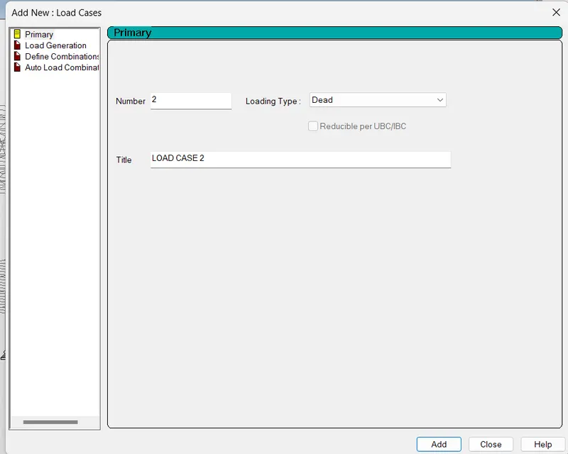
Step 2: Select Load type as Dead load and assign the self-weight for different Structural Elements under this load case.
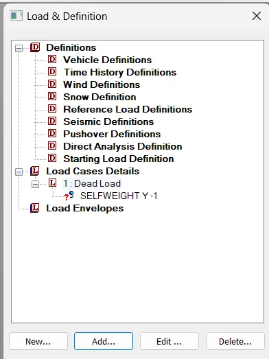
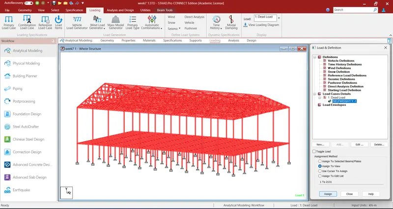
Step 3: Self-weight has been assigned to all structural elements.
Step 4: Similarly add a uniform load of 3 kN/m on the rafter.
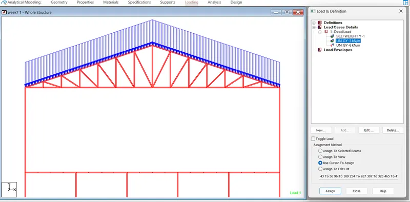
Step 5: Now add a uniform load of 6 kN/m on the Secondary Beams.
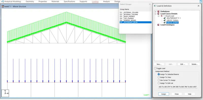
Step 6: Now, assign the Nodal load of 20 kN on point of intersection of Rafter and inclined chord.
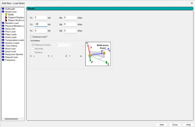
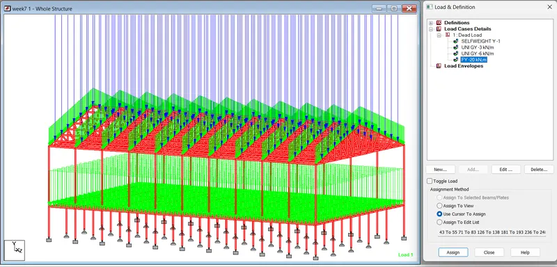
Step 7: Similarly create live load cases and assign live load as shown below:
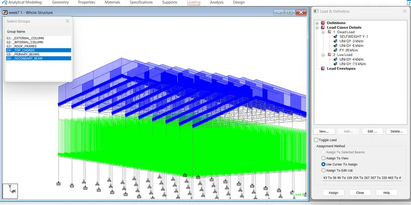
Step 8: Now define a load combination of 1.5DL+1.5LL, as shown below:
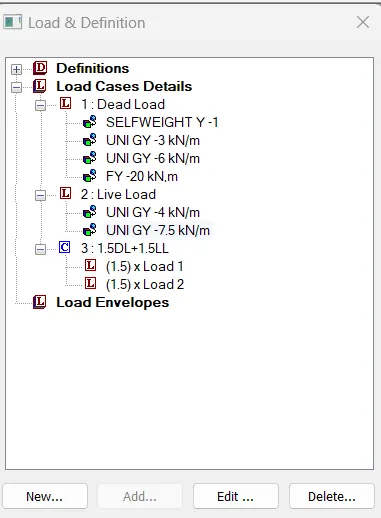
Result: All the given Dead Load and Live Load cases have been created successfully.
2)
Aim: To run the analysis and find the following results on the member mentioned
- Run the analysis
- Find the Maximum Moment in the Secondary beam for the 1.5DL+1.5LL case
- Find the Maximum Axial force on the inclined bracing and identify the member having the maximum force for the 1.5DL+1.5LL case
- Identify the Bottom chord of the Truss having Maximum shear Force & Maximum moment for the 1.5DL+1.5LL case and present the values.
Procedure:
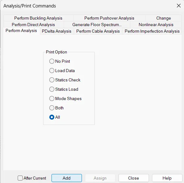
Step 1: Loading has been done already, Now run the analysis. Go to Analysis Tab, click on the last load case and click on Define Commands. A window will pop up. select All and click on Add.
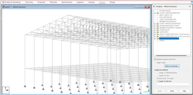
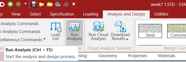
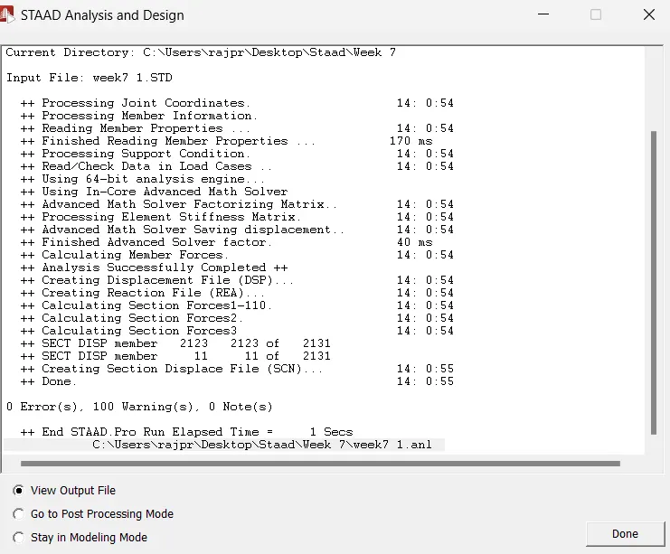
Step 2: Now Click on Run Analysis from the tab. After analysis, a window will pop up, click on View output file to view results.
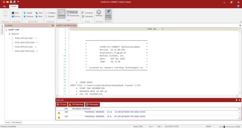
Step 3: The Final Result of the analysis will be pop-up in a different window as shown below.
Step 4: Now, we will find the Maximum moment in the secondary beam for 1.5DL + 1.5LL case. Go to Post Processing Option on Left Side. Go to View and select Secondary beam to view.
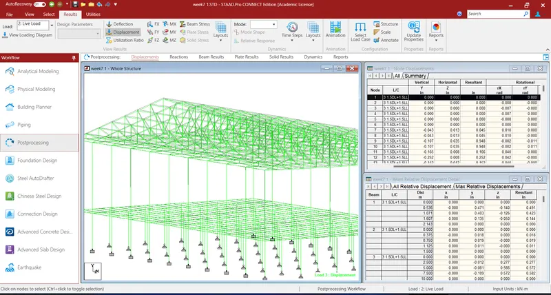
Step 5: Select only Secondary Beams, Go to Result Tab, and select Mz to view the Bending Moment Diagram.
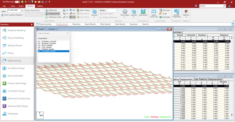
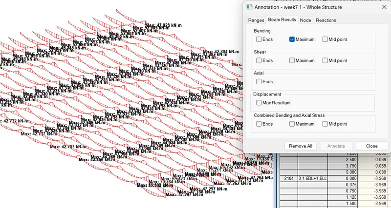
Step 6: Now go to annotate option to view the Maximum Bending Moment.
Step 7: Similarly find the maximum axial force on the inclined bracing for the 1.5DL+1.5LL Case.
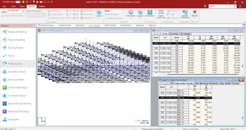
Maximum Axial force we got as 1051.851 kN on Beam Number 1904.
Step 8: Similarly find the Maximum Shear Force and Maximum Bending Moment for the bottom chord of the Roof Truss.
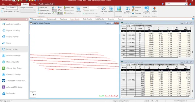
Maximum Shear Force and Maximum Bending Moment for the bottom chord of the Roof Truss as 13.735 kN and 18.616 kN-m.
Result: Following results were obtained from the analysis:
- Maximum Moment in the Secondary beam for 1.5DL+1.5LL case = 62.801 kN-m.
- Maximum Axial force on the inclined bracing and identify the member having the maximum force for 1.5DL+1.5LL case = 1051.851 kN
- Maximum ShearForce and Maximum Bending Moment for the bottom chord of the Roof Truss as 13.735 kN & 18.616 kN-m.
3)
Aim: To identify the Warnings and fix the same and run the analysis for the given STAAD File.
Procedure: After running the analysis few warning messages were displayed as shown in the below figure.
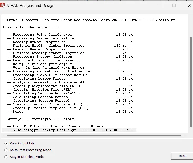
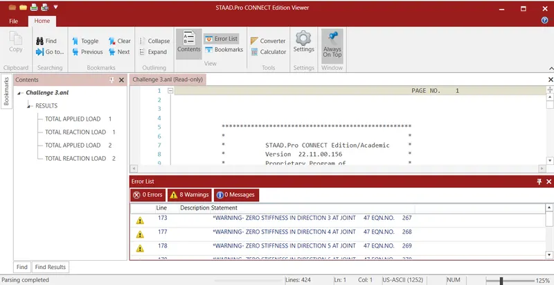
Reason for Error: A joint exists where the only structural components connected at that node are truss members, there is no rotational stiffness at that node along any of the global d.o.f.
Solution: Go to the Specification menu to create Master Node.
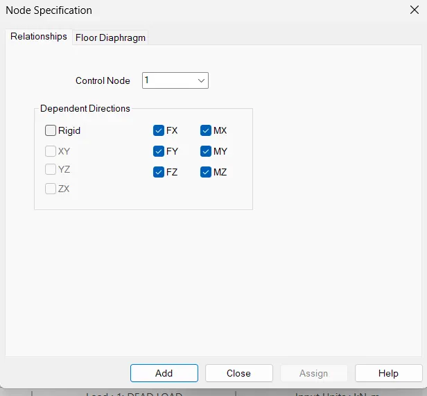
Now Run the analysis again to see if there is any warning message left. We can see that the warning message has been resolved.
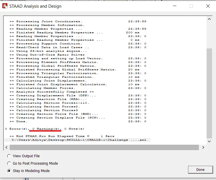
Result: Analysis has been done and 8 warning messages showing were resolved successfully and an analysis report with 0 warning messages has been obtained.
4)
Aim: To apply Design parameters for structure modeled for code IS 800:2007.
- Effective Length Lx, Ly, Lz for beams, Truss elements
- Effective length factors Ky, Kz for Columns
- Apply other design parameters for respective members
Procedure:
Step 1: Go to the analysis and design tab, select all the structural members and assign steel as the basic material. On the right-hand side, select the IS 800 code as shown in the below figure.
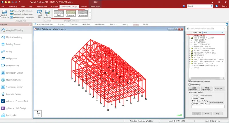
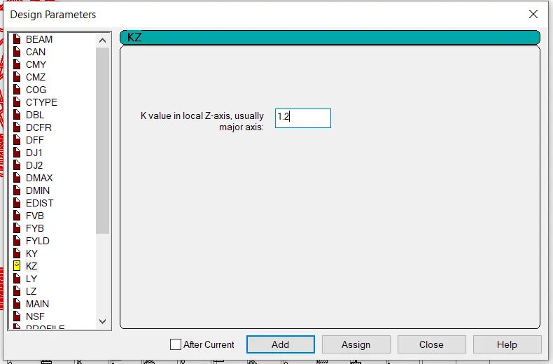
Step 2: Now, define the parameter for the like Ly, Lz for beams and trusses; Ky, Kz for columns.
Step 3: Now, run the analysis again to see that there is no error.
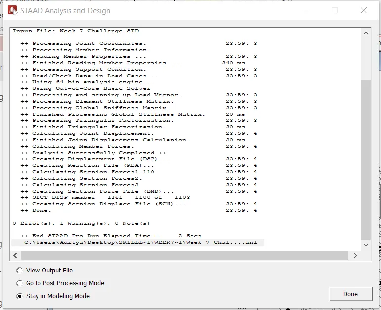
Result: The design parameter has been successfully applied to the modeled structure in STAAD PRO.