Week 8 - Challenge 4 - Coin Holder Design
AIM:
To create the coin holder plastic component through the given class-A surface.
OBJECTIVE:
- To make sure that the model meets the requirements of the draft angle.
- To create the tooling axis using bisecting method.
- To perform Draft analysis on the given class A surface.
- To create the required class B and Class C surfaces.
- To obtain a solid body from the surface using close surface feature of the part design.
CLASS A SURFACE:
- Class A surfaces are those surfaces which are curvature continous while providing the simplest mathematical representation needed for the desired shapeand does not have any undesirable waviness.
- The class A surface is used to begin the design of the given product.
- All the furthee needed surfaces of the component are created based on class A surface.
CLASS B SURFACE:
- The class B surface will be created from class A surface, by considering the component thickness.
- The class B surface should resemble as the offsetted class A surface.
CLASS C SURFACE:
- The class C surface is used to close and bind both class A&B surfaces.
TOOLING AXIS:
Procedure:
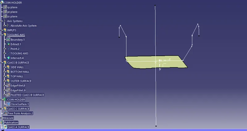
- Initially by using boundary and intersection command, the direction of the tooling axis will be considered.
- A base surface from the class A will be extracted to create the intuited tooling axis.
- Then by using the line command,a tooling axis will be created inthe desired direction.
Procedure for creating class B surface:
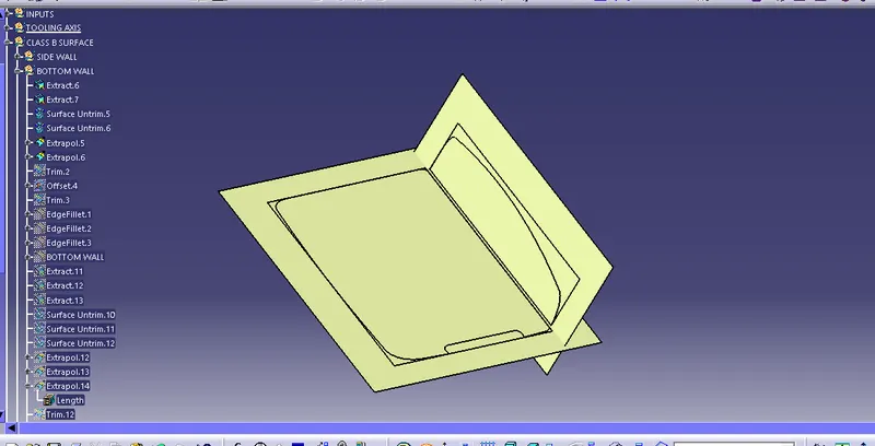
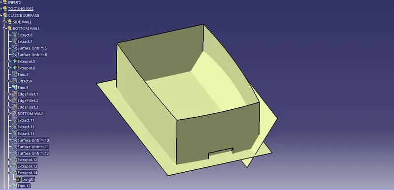
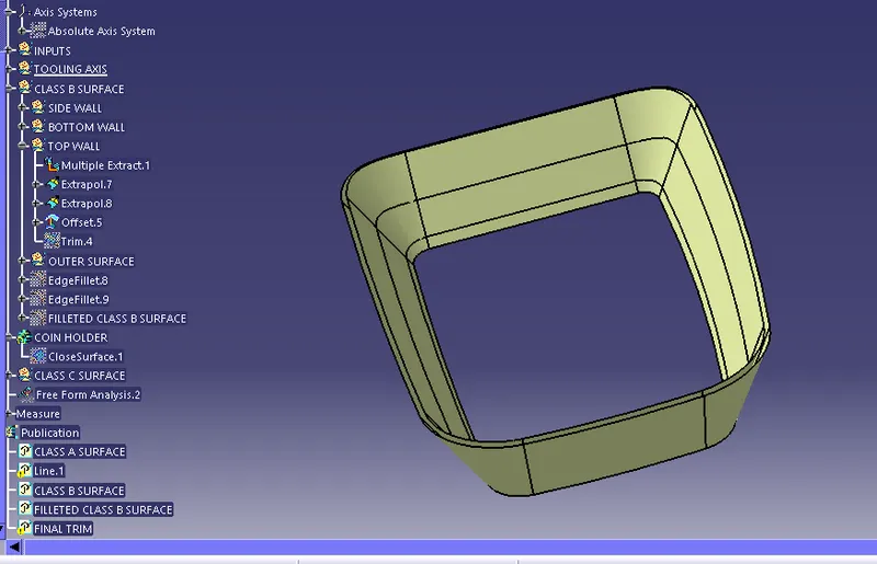
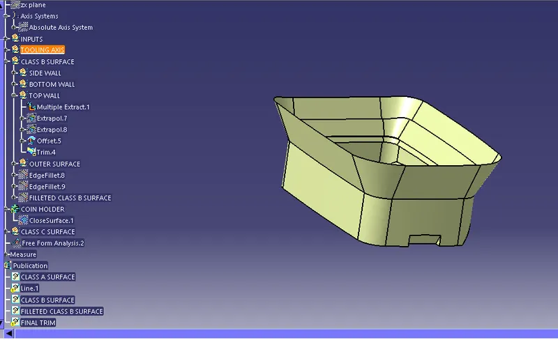
- In this particular component to create class B surface, the part has been divided in to 4 major parts.
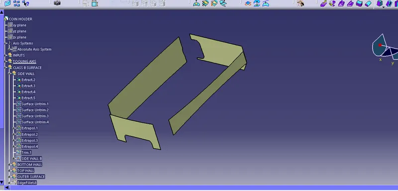
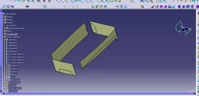
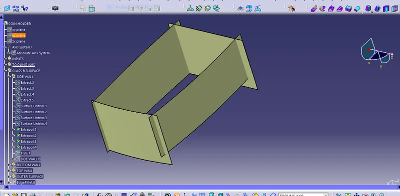
- Each group of faces has been extracted seperately,untrimmed,extrapolated and trimmed after offsetting with respect to class A surface by considering the given component thickness.
EXRACTED:
UNTRIM:
EXTRAPOLATE:
TRIM & OFFSETTED:
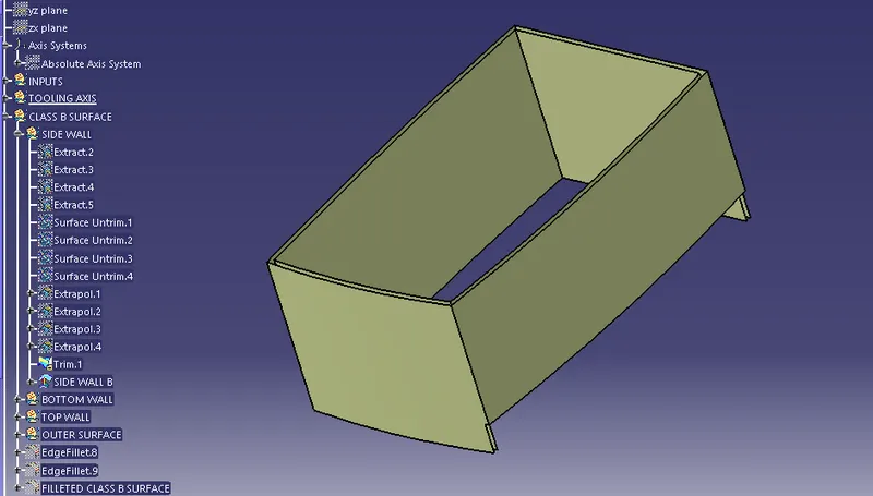
So the same as above all four major parts are extracted seperately and carried out the same process to create the B surface.The pictures will be shown below sequentially:
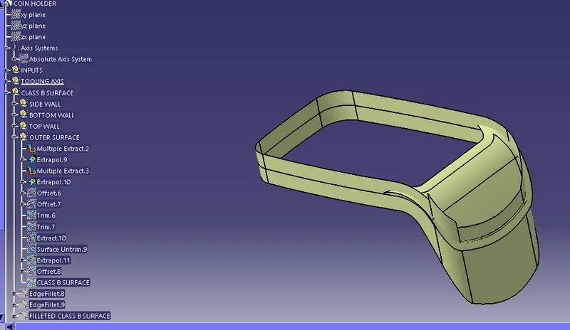
FINAL B SURFACE:
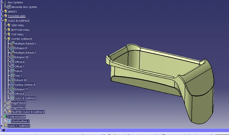
Procedure to create Class C surface:
- Class C surface is used to bind class A and the created B surfaces together,so that we can create a required closed surface.
- The outer flange of the class A was used in class C creation, the outer boundary and the faces adjacent to the boundary will be extracted.
- The sweep operation will be performed with the help of with the reference surface option to create the sweeo,i.e the class C surface.
- The hole present in the component is also create by the same steps as mentioned above.
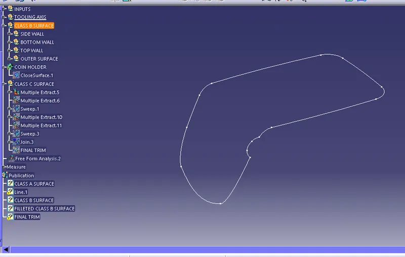
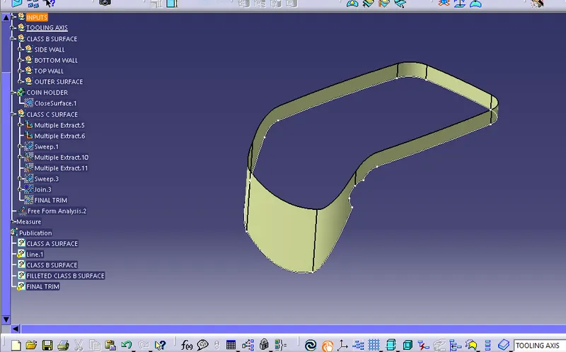
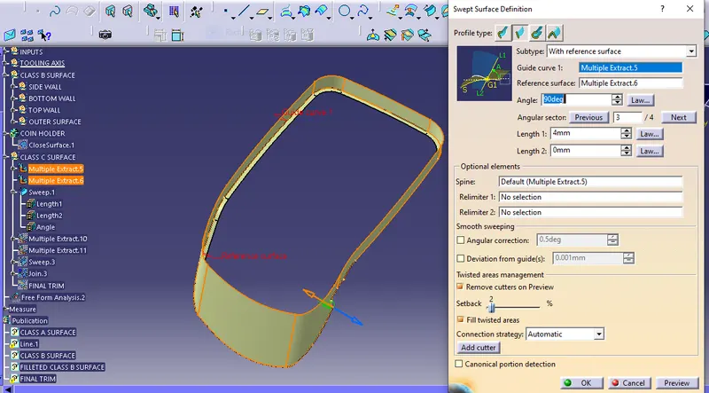
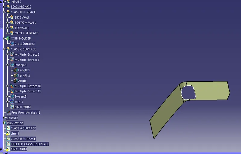
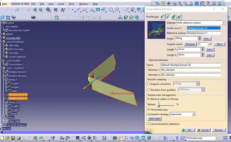
Then finally the class C surface will be joined with class A.Then the final trim has been performed to get the final component.
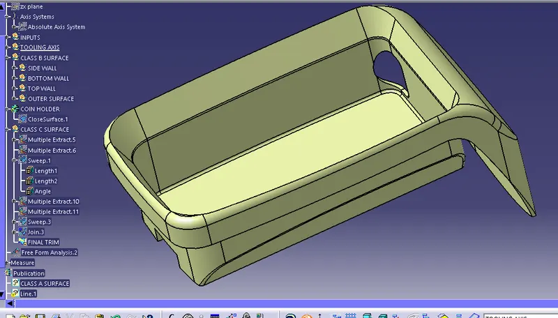
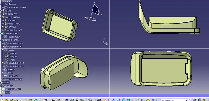
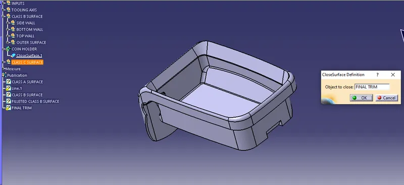
So to create the solid model, close surface option from part design is used to create the final output.
DRAFT ANALYSIS REPORT:
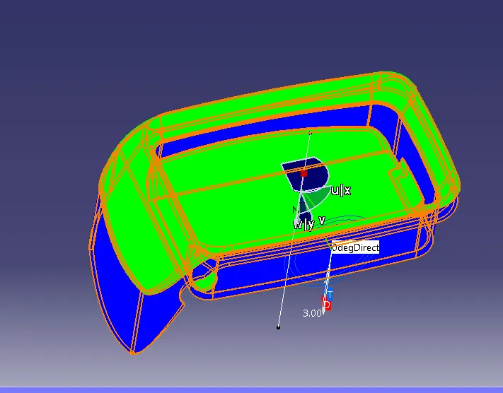
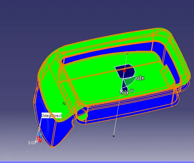
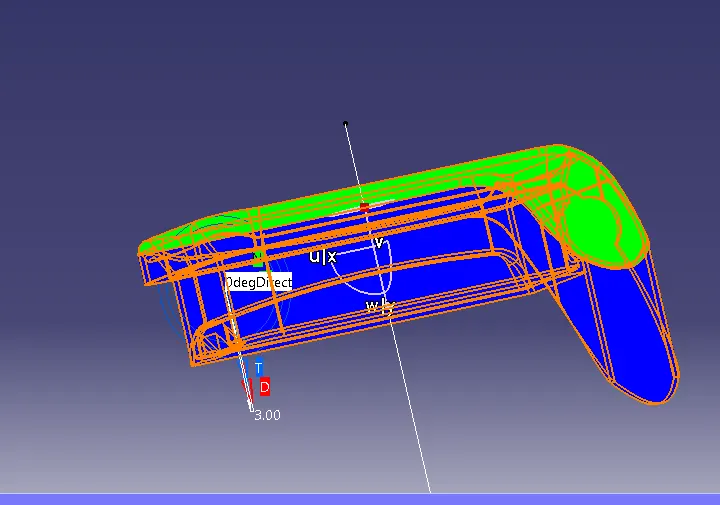
The Draft analysis has been performed for the created tooling axis as explained above.But the draft is not getting cleared for some face of the component.Please take a look on the below picture,
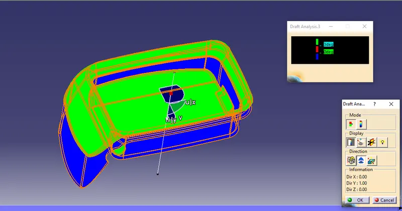
So from the above image we can see that,certain faces are not cleared with the created tooling axis.This is because the faces which are in color blue are at 0 deg, which means there is not draft involved in the class A surface itself.So to overcome this problem,while checking the draft analysis for the class A itself.The Class A designer should be informed and discussed based on the component assembly and tooling,that these faces has to be designed with atleast minimum draft to avoild mold defects and high costing.The picture will be posted below which can confirm the reason for not clearing,