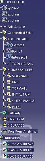
Week 8 - Challenge 4 - Coin Holder Design
OBJECTIVE:Create the COIN HOLDER DESIGN Plastic component through the given Class-A surface. To begin with, the tooling axis for the given Class-A Surface should be created meeting the requirements of the draft angle and at the end perform the Draft analysis on the model.
CLASS A SURFACE: Class-A is a term used in specifically in automotive design. It describes the final production surface data for the aesthetic parts of the car.
CLASS B SURFACE: This surface is created by taking the offset fom the class A surface and it is the surface on which all the mountings and ribs are created
CLASS C SURFACE: It is the surface which joins class A and class B together
TOOLING AXIS: It is the direction in which core and cavity opens & closes
PROCEDURE:
- check the continuity of class A surface and ensure that it was properly joined without any discontinuity.this can be done by using join or boundary comand in CATIA v5
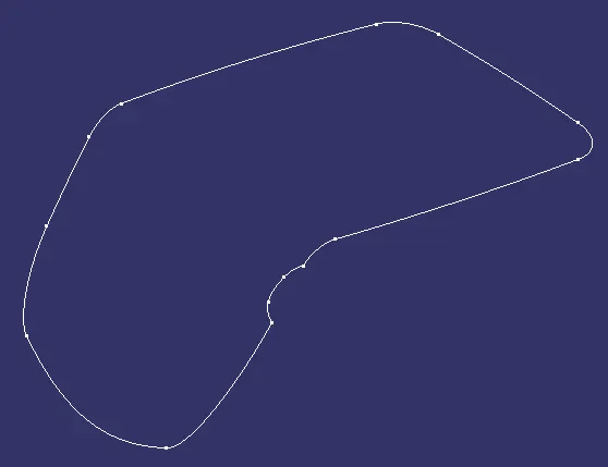
- Extracting the boundary of given class A surface and we also check continuity visually.
- we have to give even wall thickness to avoid flow lines after the manufacturing process
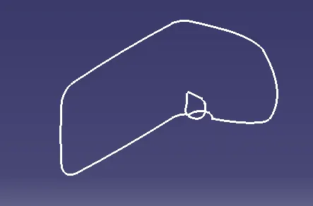
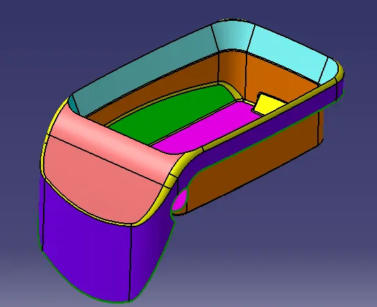
the first step to create the
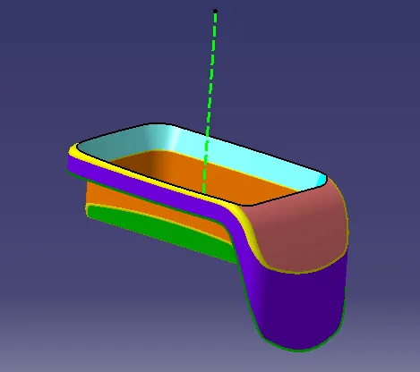
Tooling axis
- to decide the tooling axis direction by analyzing model visually to see which direction is most suitable for tooling axis
- extract the base surface from class A surface and create a point on the extracted surface using point command
- create a new axis system using above point as the origin and create a line normal to the surface this line is the tooling axis
CLASS B SURFACE
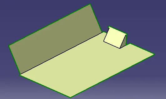
- SIDE WALLS: CLASS B surface is created using class A surface and firstly extract the side walls from the class A surface untrim and extrapolate the above surfaces using point continuity
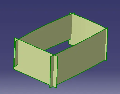
- trim the surfaces together to get single surface resembling the class A and give necessary fillets and offset it outwards to 2.5mm
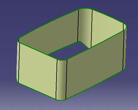
- BASE : extract the sides of the base fro class A surface and extropolate it and trim the surfaces together to get single surface and offset it to 2.5m
UPPER WALL:
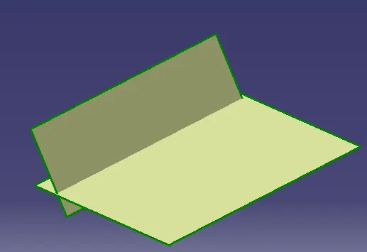
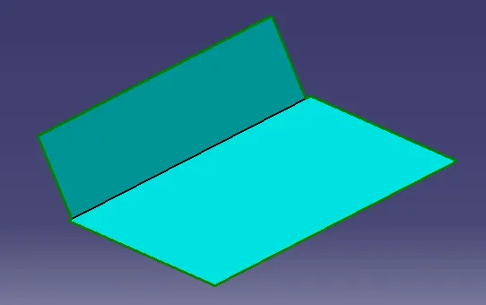
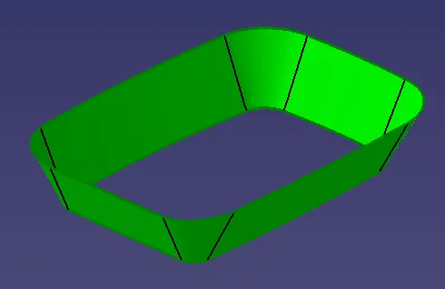
- Extract the upper wall surfaces from class A surface using ulti extract feature iincluding the fillets and extrapolate the above surface using point continuity and offset of 2.5 mm outwards
OUTER FLANGE:
- The outer flange surface is created in two steps,firstly extract the surface from class A surface and extrapolate the above extracted surface using curvature and point continuity
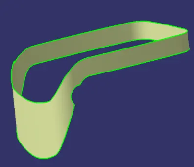
- extarct the remaining surfaces of the outer flange feom class A surface and untrim the above extracted surfaces and join them and extrapolate the resulting surface
- offset the above surfaces inwards 2.5mm and trim the surfaces together

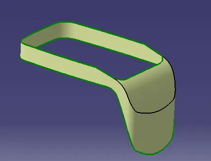
- trim the base and the side wall surfaces using trim command
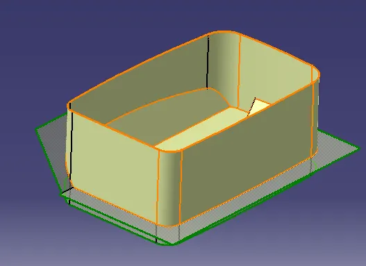
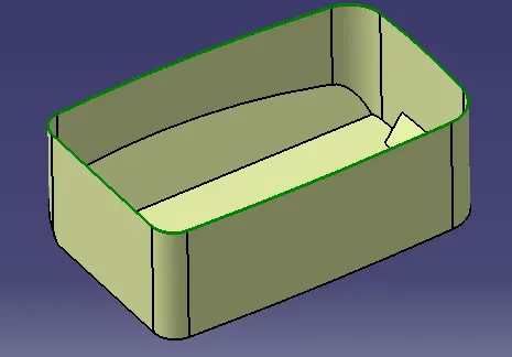
- trim the above surface and the outer flange surface together using trim feature
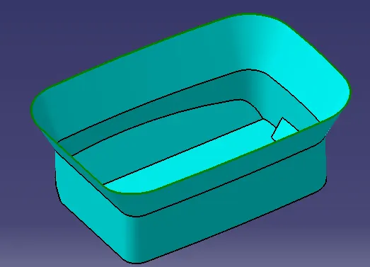
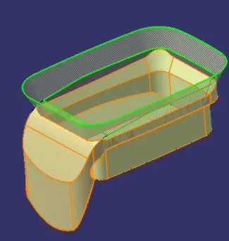
- extract the small flat surface at the top from class A surface and untim and extrapolate it and trim it with the last trimed surface
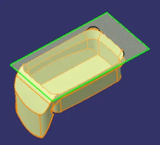
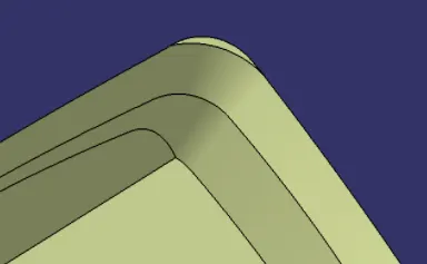
finally trim the unwanted surfaces and give necessary fillets
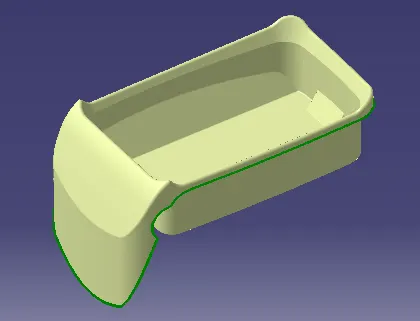
CLASS C SURFACE:
- Extract the enclousing walls of the outer flange using multiple extract feature
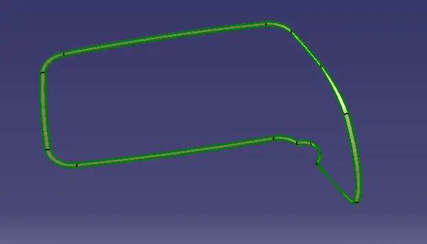
- extract the boundary of the class A surface
- use sweep feature with referance surface and choose the guide curve as the above extracted boundary and reference surface as extracted surface from class A surface and choose angle as 90deg
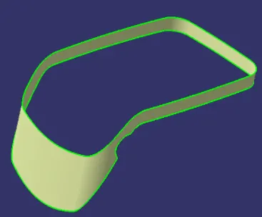
Final trims
- Trim class B surface and class c surface And then trim the class A with the above enclosed surface
- Use the close surface feature,the final closed surface is coverted to solid body
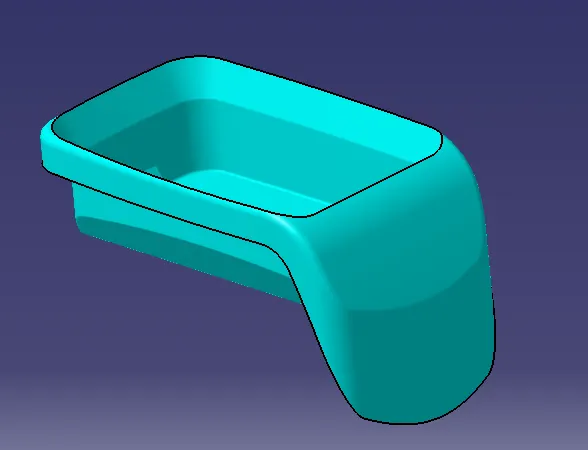
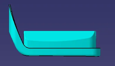
DIFFERENT VIEWS
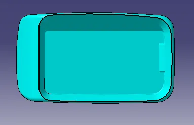
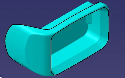
DRAFT ANALYSIS
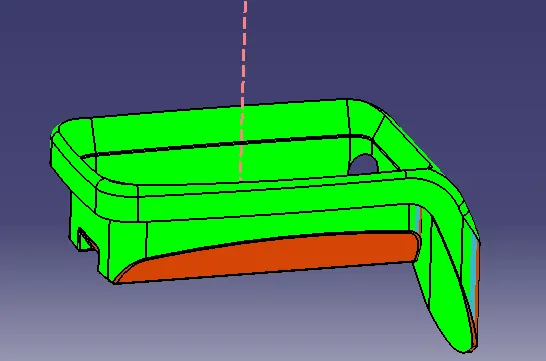
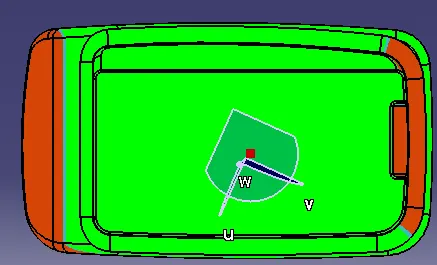
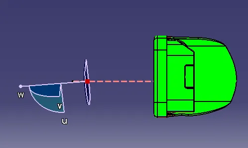
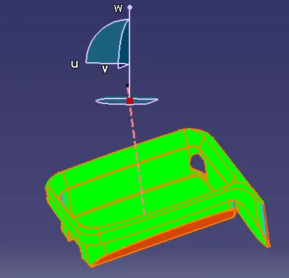
Go to INSERT-ANALYSIS-FEATURE DRAFT ANALYSIS and move the compass towards the tooling axis and chnage the range to
Remarks
There are lot of surfaces in different colour that indicates 0 draft angle, thus these surfaces should be provided with some draft angle in order to reduce defects during manufacturing
PART BODY