Week 8 - Challenge 4 - Coin Holder Design
COIN HOLDER DESIGN&DRAFT ANALYSIS
AIM- Creating the coin holder plastic component through the class A surface.
OBJECTIVE-
- Creating the B and C surface.
- Creating the tooling axis.
- Perform the draft analysis class A, B, and final component.
- Take the thickness of the component 2.5mm
INTRODUCTION-
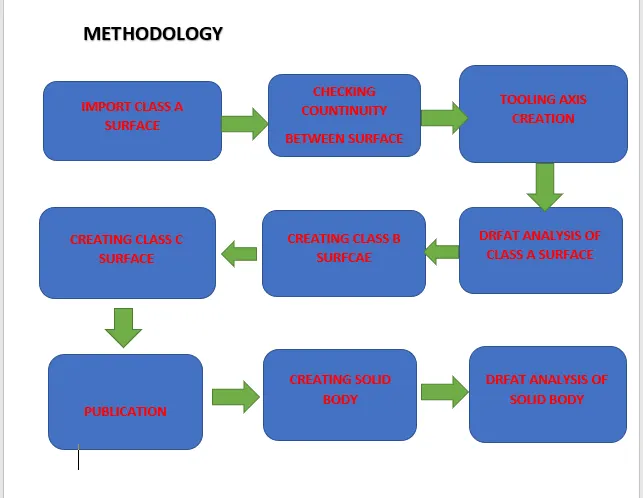
The input of the product designer is in the form of the class A surface. The role of the product designer is to create the B surface and C surfaces keeping all the aspects for the mould.
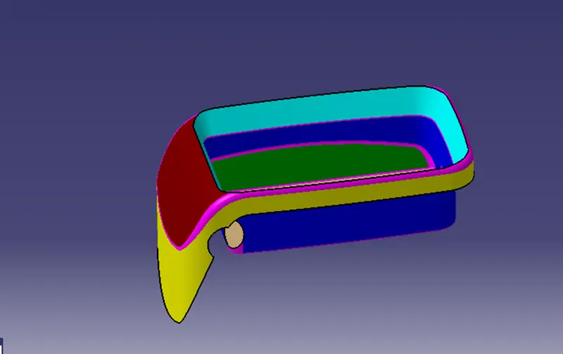
CLASS A SURFACE- A surface made by the designer which is given as an input to the plastic molder to work on. It is aesthetic surface and outer most surface. Visual surface with aesthetic look, the surface which has no ribs, slots etc. Class surface is made from scanned data with different software like alias. Surface which is curvature called class A.
CLASS B SURFACE- A surface below a certain thickness from the class A surface to class B surface. This is the surface that contains engineering aspects of a model. surface don’t have texture, need to be create with respect to class A surface. Having all features like ribs, slots in B side surface only. Surface which is having tangent continuity is called as B surface.
CLASS C SURFACE-A surface that is joined class A and class B surface.
GIVEN CLASS A SURFACE
PROCEDURE: -
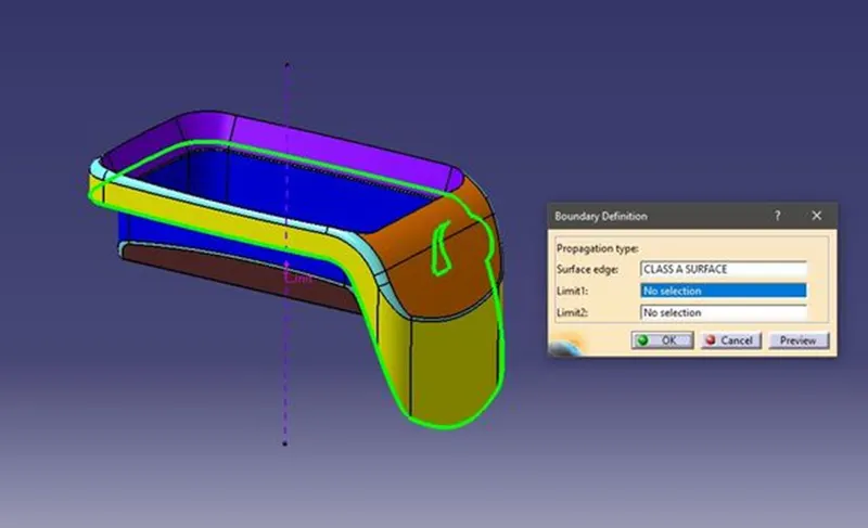
CONTUNITY CHECK-
Input the class A surface. After receiving the class, a surface checks the continuity of the given class a surface to ensure that there is no discontinuity in the class a surface. This can be checked using join or boundary command.
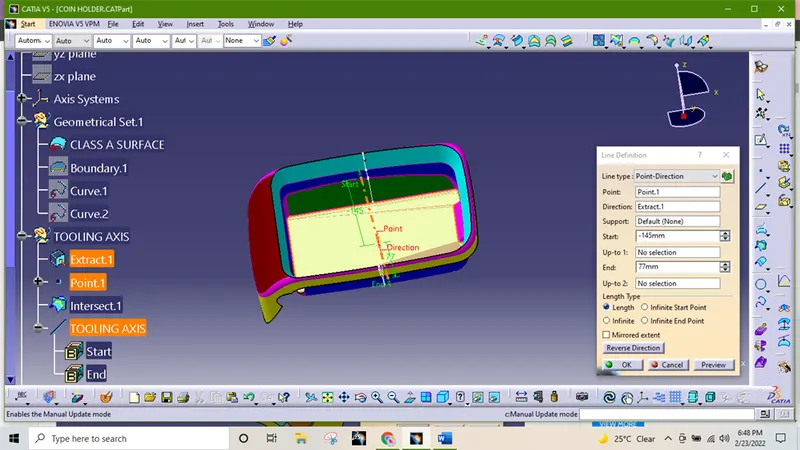
TOOLING AXIS CREATION-
Extract the bottom surface of the given class A surface.
Create the point using surface commend the axis system at that point the surface using the axis system definition to selecting a point. Now create an intersection in ZY plane. Create a line along the Y direction using that point the line is created is the required tooling axis.
CLASS B SURFACE CREATION-
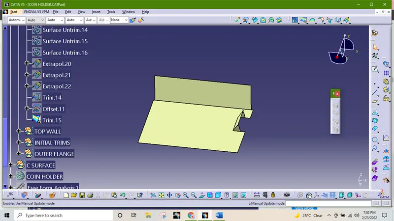
BASE SURFACE-
- Extract the base surface from the class A surface.
- Untrim the extracted surface and extrapolate the surface with point continuity such that it intersects with each other.
- Trim the surface and offset the surface 2.5mm.
SIDE WALLS-
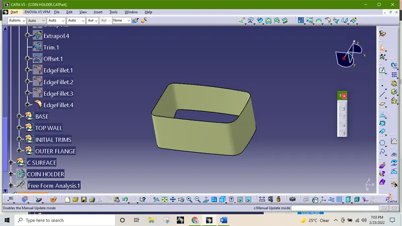
- Extract the side surface from the class A surface.
- Untrim the extracted surface and the extrapolate the surface with point continuity it intersects with each other.
- Trim the surface and offset the surface 2.5mm.
- Extract the inner projection from class A surface, untrim it and extrapolate with point continuity.
- Apply appropriate edge fillet.
TOP SURFACE-
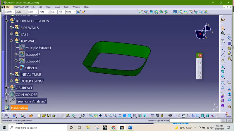
- Use multiple extract to extract all the top surface.
- Extrapolate the surface with point continuity.
- Offset the extrapolated surface outwards 2.5mm.
- User Surface (use multiple extract option to extract all the outer surface.)
- Extrapolate the surface and offset it 2.5mm.
TRIMS-
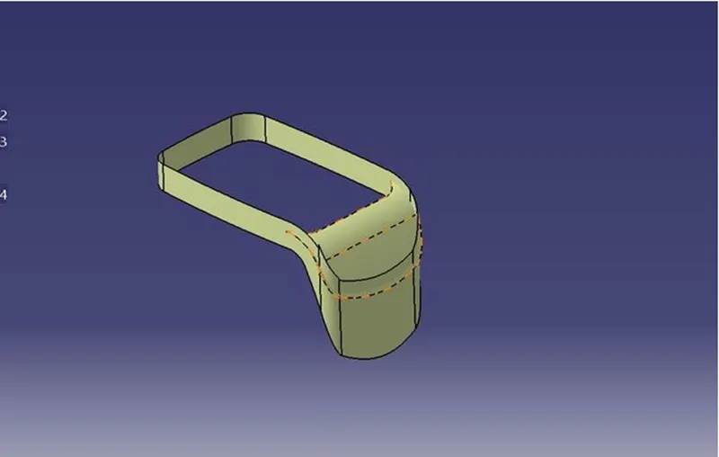
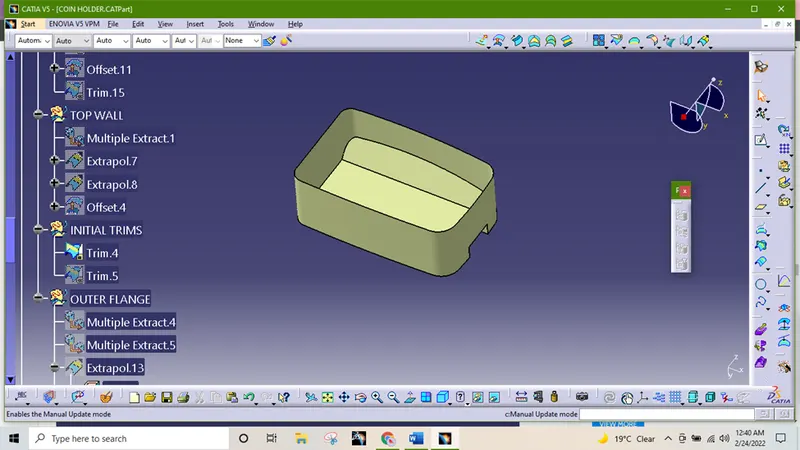
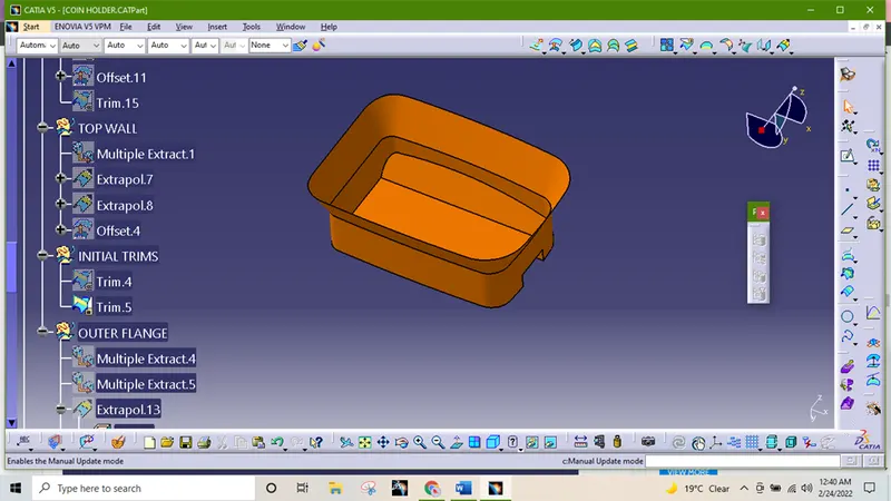
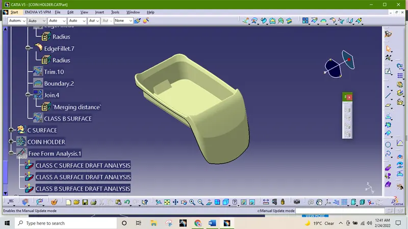
- Trim the base surface and side walls together.
- Apply edge fillets.
- Trim the filleted surface with top walls.
- Trim the final outer flange with previously trimmed surface.
- Apply fillet when required.
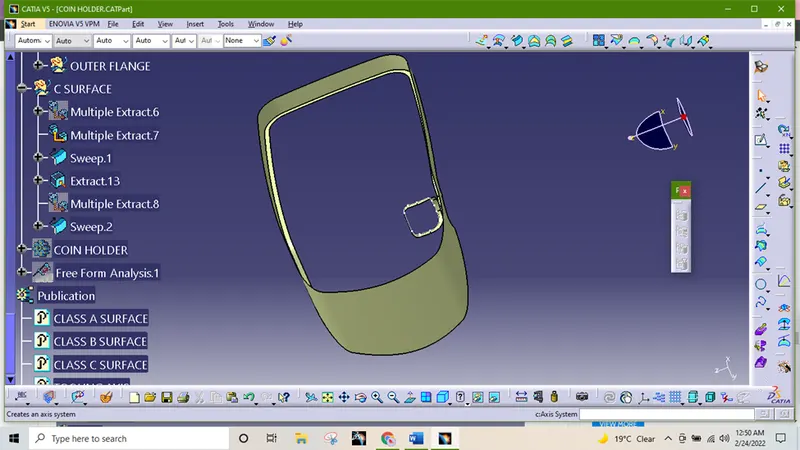
CLASS C CREATION-
- Using the multiple extract option extract the boundary class a surface.
- Using the multiple extract option extract the outer surface.
- Use the sweep option to create the class c surface with the two multiple extracts as input.
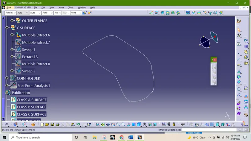
- Create the boundary of the inner hole in the class C surface.
- Sweep the boundary and trim the surface to get final class C surface.
- Trim the class C surface with B and A surface.
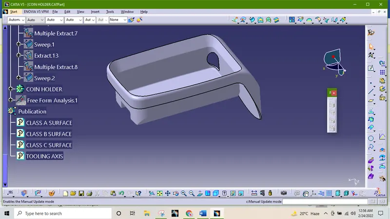
Final solid body-
Check for whether any open boundaries or not, if not then go to part design close surface option and close the body to make it solid.
DRAFT ANALYSIS-
- Final plastic parts are the nominal draft angle is 3 degrees but even 7degree is allowed for the subassemblies like ribs and slots.
- Insert< Analysis< Feature draft analysis
- First the compass is moved to the part which used to define the tooling axis new current draft direction then lock the draft direction using the lock icon.
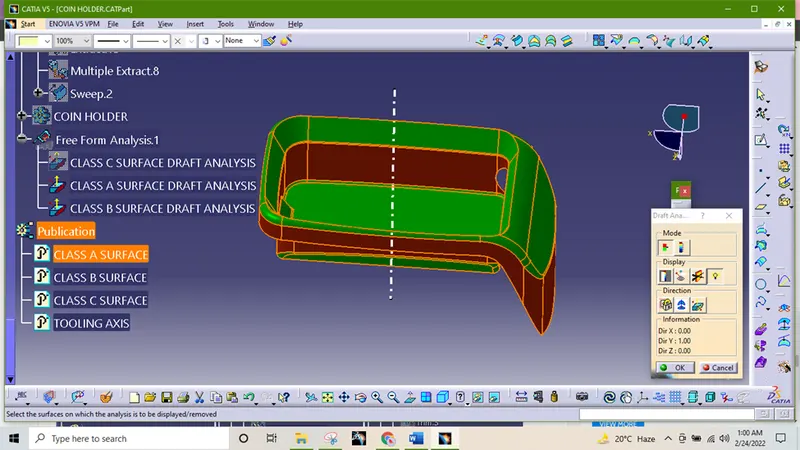
- The color of the chart indicates the draft if the color is indicated that means the part passes and used for further operation.
- By using the analysis under the running point icon, we can check draft angle at the various surface of the component.
- If the surface satisfied the draft angle, then it shows the green color if not appears in red color.
CLASS A SURFACE DRAFT ANALYSIS-
Draft analysis is performed class A to check the validity of the tooling axis. During draft analysis it was observed that bin walls are having 90 deg angles with base. There is no minimum draft angle given to the walls. Since we are not authorized to make change in class a surface, we can inform class A designer to give minimum draft angle.
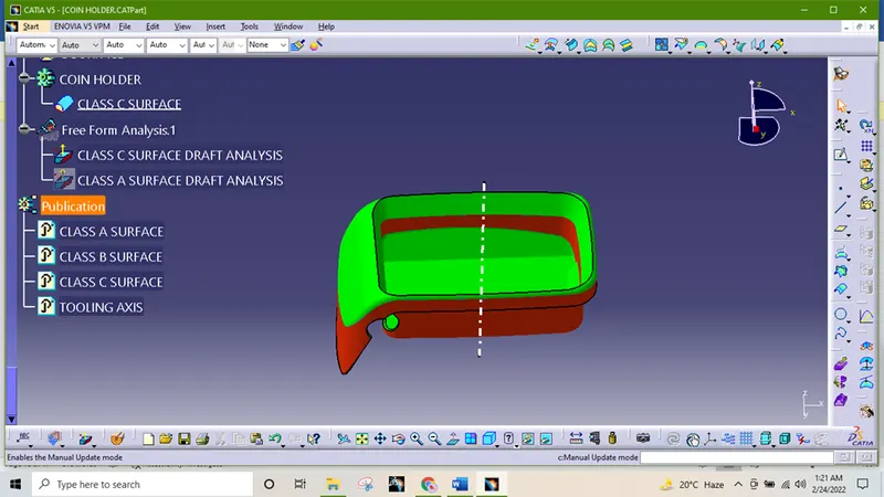
CLASS C SURFACE DRAFT ANALYSIS-
Draft analysis is done with solid body (Class C surface) to check manufacturing ability. The bin walls are having zero draft angle with tooling axis. this will be ignored since it is given class A surface.
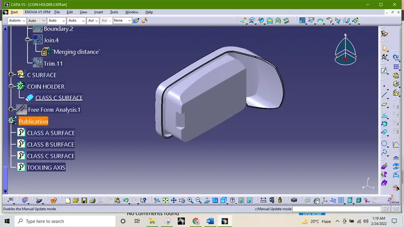
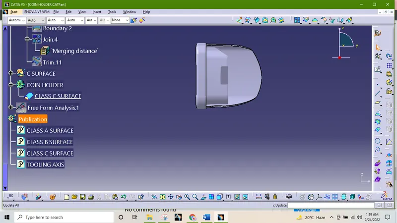
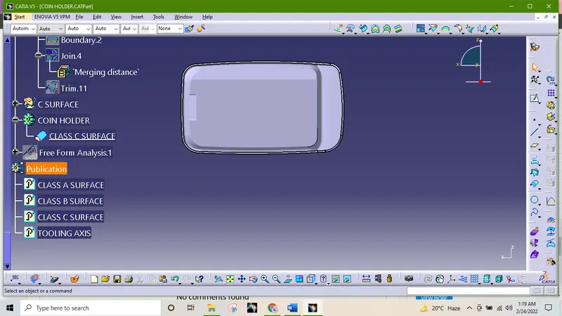
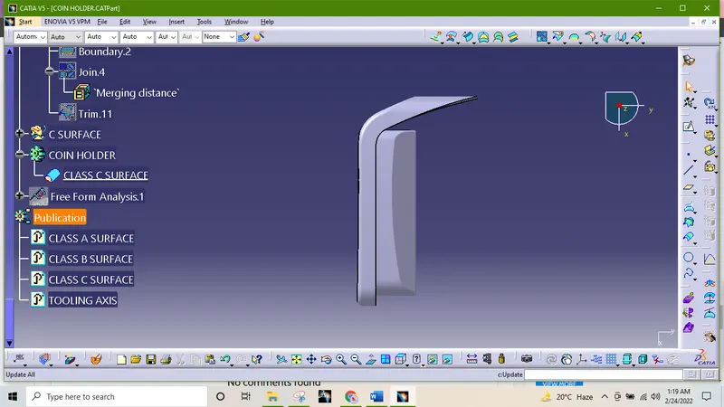
DESIGN VIEW
ISOMETRIC VIEW
FRONT VIEW
RIGHT SIDE VIEW
TOPVIEW
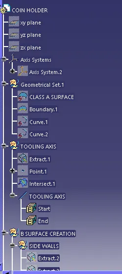
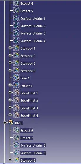
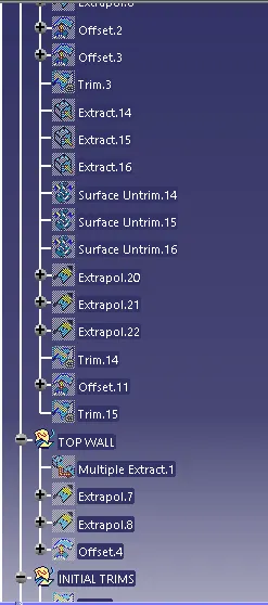
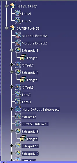
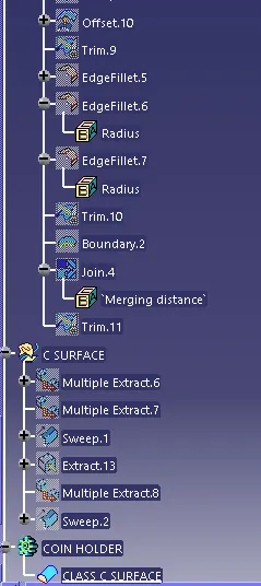
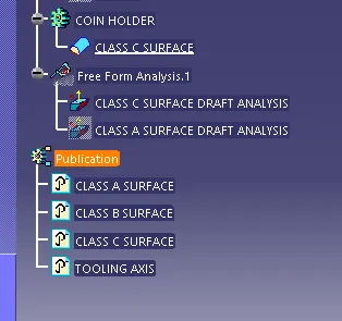
FEATURE TREE
CONCLUSION-
Created the plastic design for added thickness and generated the draft analysis on a solid surface for center console coin holder.