Week 8 - Challenge 4 - Coin Holder Design
COIN HOLDER DESIGN
The main objective is to create a tooling axis for a given Coin Holder by satisfying the construction of surfaces and to perform draft analysis to check if the part has given draft to the surfaces which are lying parallel to the tooling axis. Also, to create CLASS B and CLASS C surfaces from the given CLASS A surface of the Coin Holder to create the solid part with proper draft standards.
DRAFT :
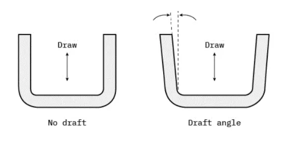
In engineering, draft is the amount of taper given to the surface of moulded or cast parts perpendicular to the parting line.
The in build draft analysis tool used in CATIA to ensure that the faces are taper with the respect to the tooling axis. The tooling axis is the direction of mould part ejection.
The draft is provided on both core and cavity sides of the parts, which are produced using moulding, to reduce damage to the surfaces during ejection.
Usually the draft angle should be 3 degrees.
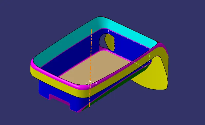
Given CLASS A Surface
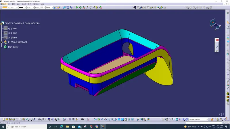
To simply work on the given part, first we have to divide it into identical portions that we are going to work on it. Here the given CLASS A surface of the coin holder is divided into five sections and coloured in the above picture.
Firstly, we are required to determine the tooling for the given CLASS A surface. After creating the tooling axis, we have to conduct draft analysis on it. Making sure that all surface which to correspond to mould opening should satisfy the draft standard of mould design.
Later, Create the CLASS B and CLASS C surface with reference to the CLASS A surface and create the final trim. Then the part is thickened with the material.
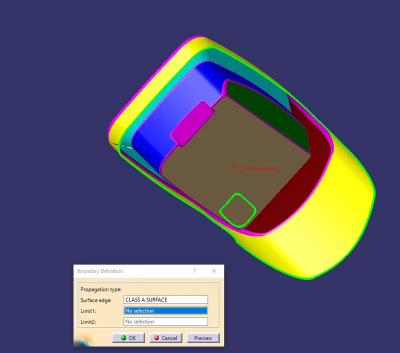
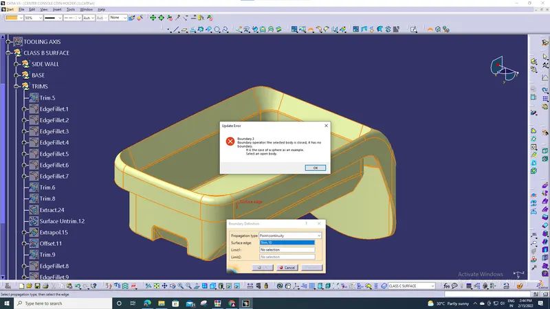
Check for open boundaries
TOOLING AXIS
Create a point at the centre of the base and insert an axis system.
Create a dummy tooling axis through it.
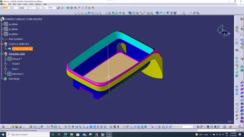
If we check, there is no surface is drafted with that axis. All surfaces around it are laying normal to it.
Hence, it is observed that no draft is given to the CLASS A surface, we are not able to modify it. So, there is no possible way to create the tooling axis along X and Y directions. If we create, both lines lie in the same point and same direction. Therefore, the obtained dummy tooling axis is the tooling axis for the given CLASS A surface.
DRAFT ANALYSIS
Open draft analysis and select the compass and coincide it with the tooling axis.
After selecting the tooling axis, position the compass along the tooling axis and lock it.
Now select the surface to be drafted and check the draft with colour codes.
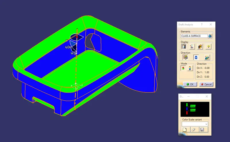
Here, it is observed that, the vertical walls are having no draft angle which are indicated by the blue colour. This means, CLASS A surface designer, does not provide the draft to the surface. We are not able to modify this without higher authorities in industry point of view.
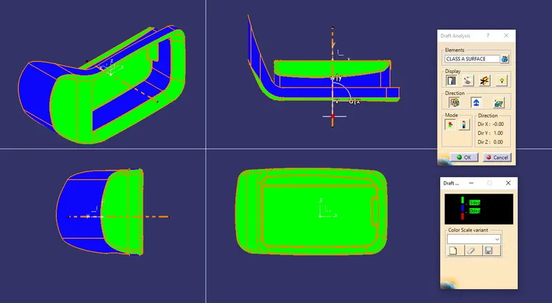
Here, there are no negative draft in the CLASS A surface. Therefore, the tooling axis is valid.
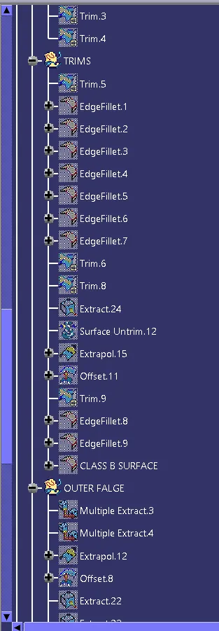
CLASS B SURFACE
Extract the side walls, un trim them and extrapolate
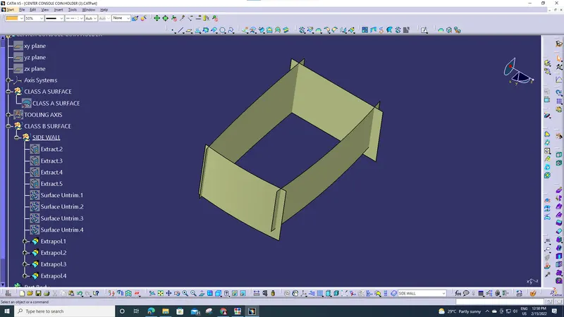
Trim the edges and offset to 2.5 mm
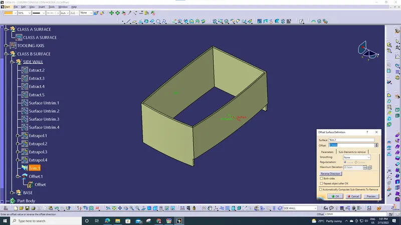
Also do same for the base
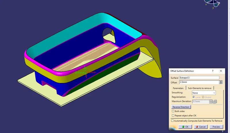
Also do same for the features included in the base
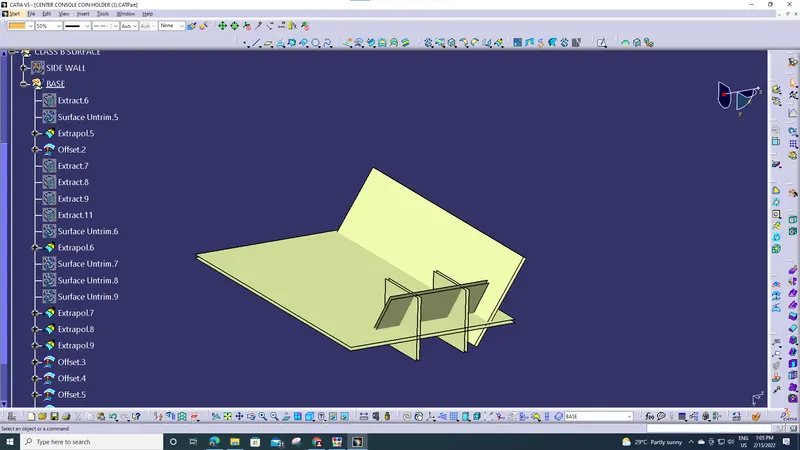
Create the required trims
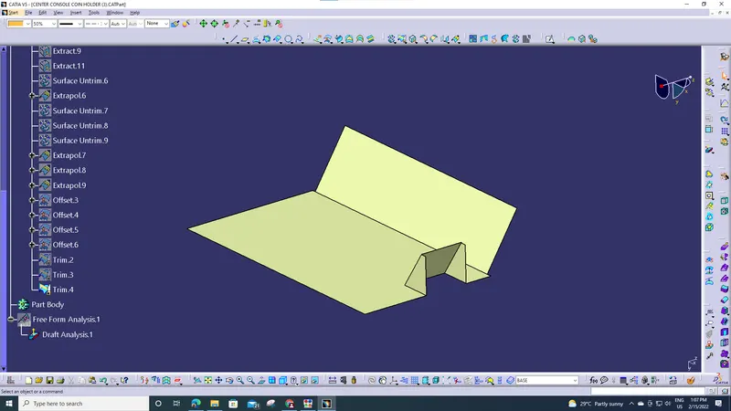
Trim both the base and side walls
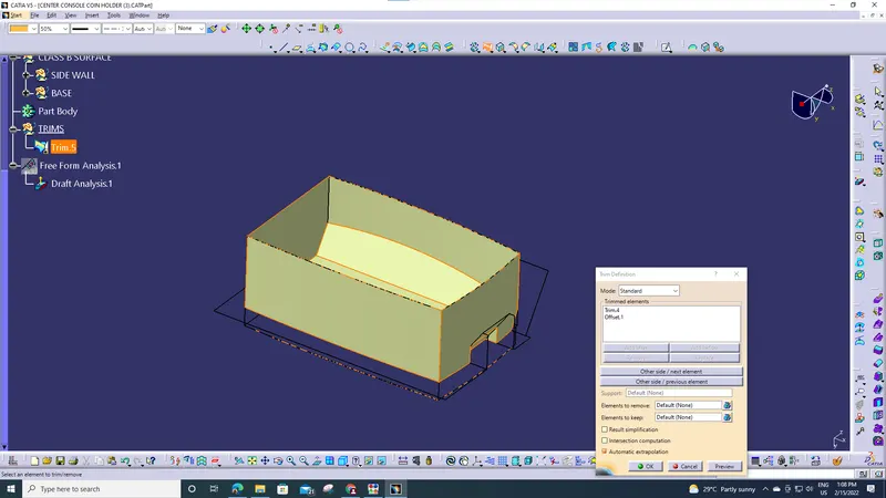
Extract the wall surfaces, extrapolate and create at an offset
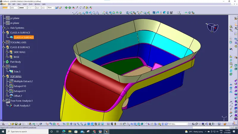
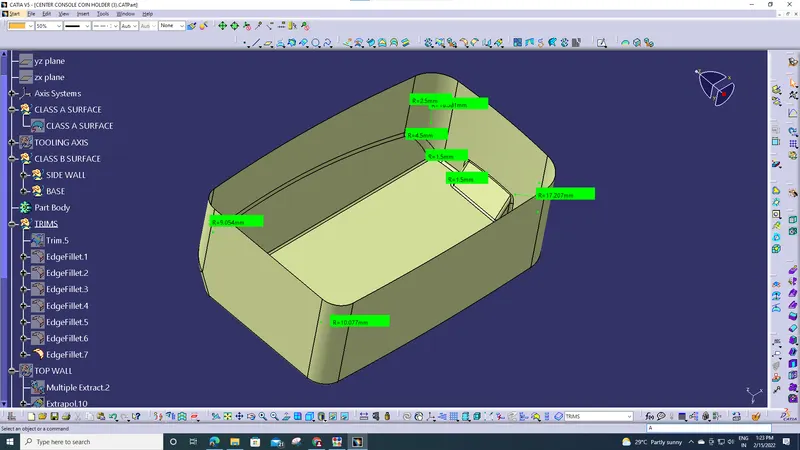
Create fillets with reference to the CLASS A surface
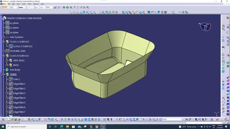
Trim the wall with initial trims
Extract the outer flange surface and extrapolate. Some surfaces are not able to extrapolate, then take them as separate sections, extract them individually
Finally, offset the surfaces
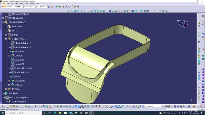
Trim the unwanted sections
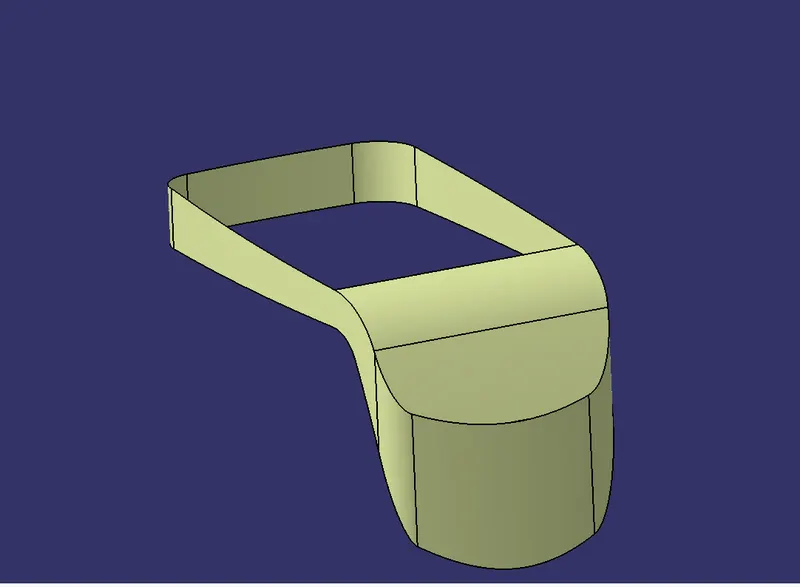
Trim both sections
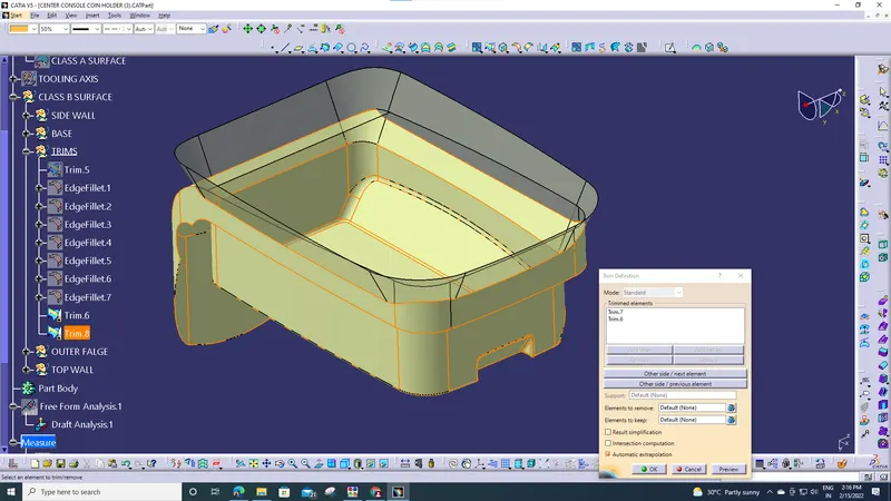
It is observed that there is a small patch
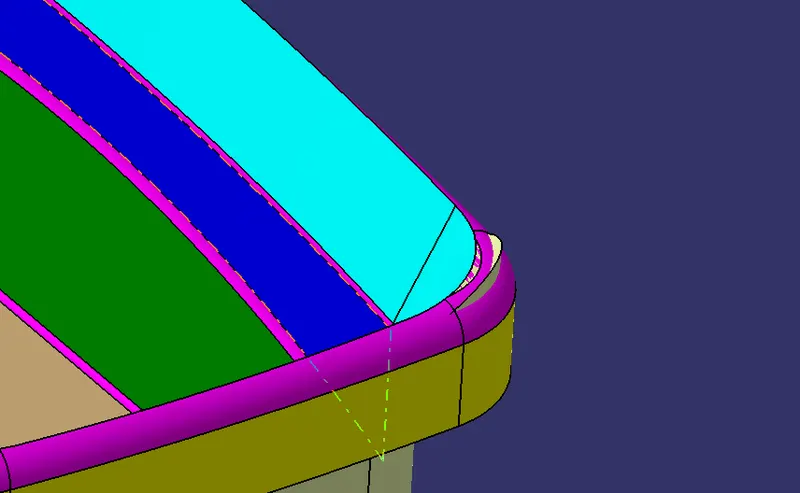
Apply required fillets
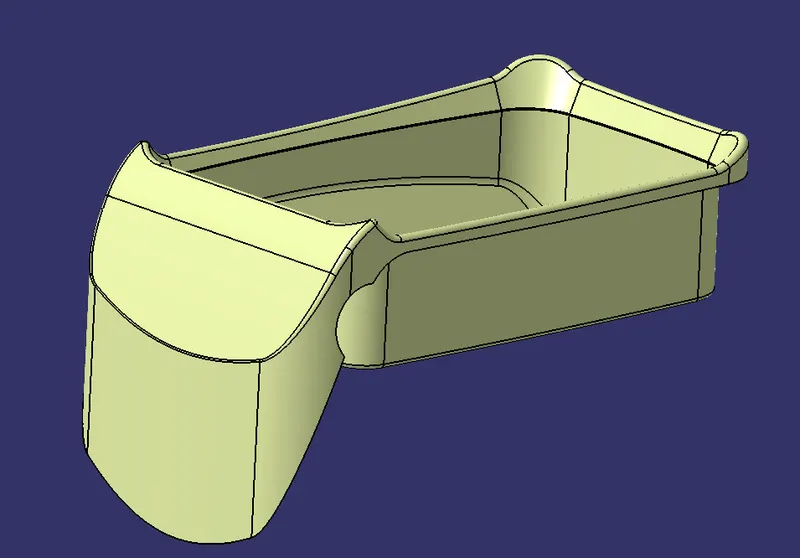
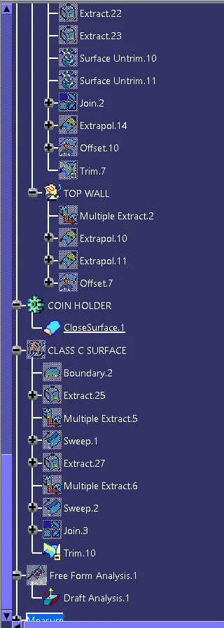
CLASS C SURFACE
For class C surface creation, extract the boundary and surface as shown in the picture
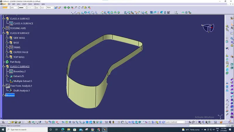
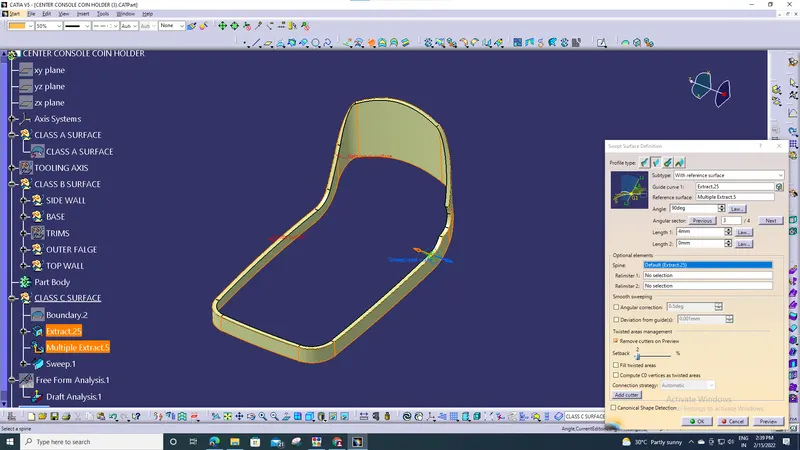
Swept the guide curve with reference to the surface
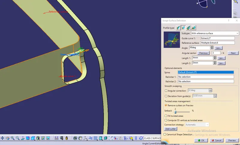
Also do the same for the hole
Join the CLASS A surface with the CLASS C surface
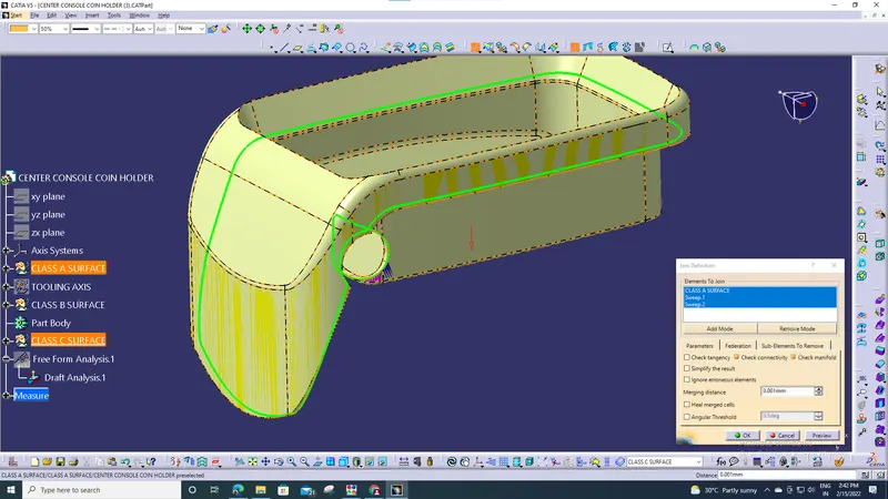
Trim CLASS B surface with the joined surface
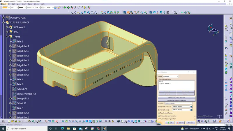
No Open gaps are found. Therefore, the all surfaces are created without error
Finally, create the solid part
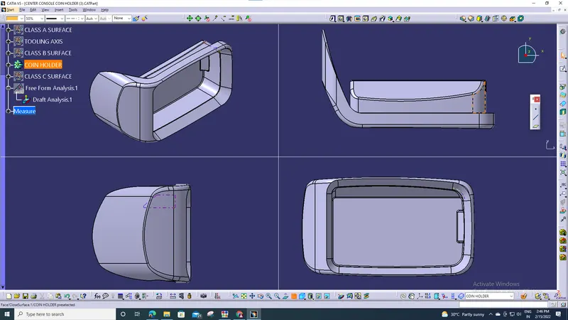
DRAFT ANALYSIS
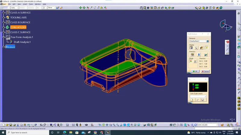
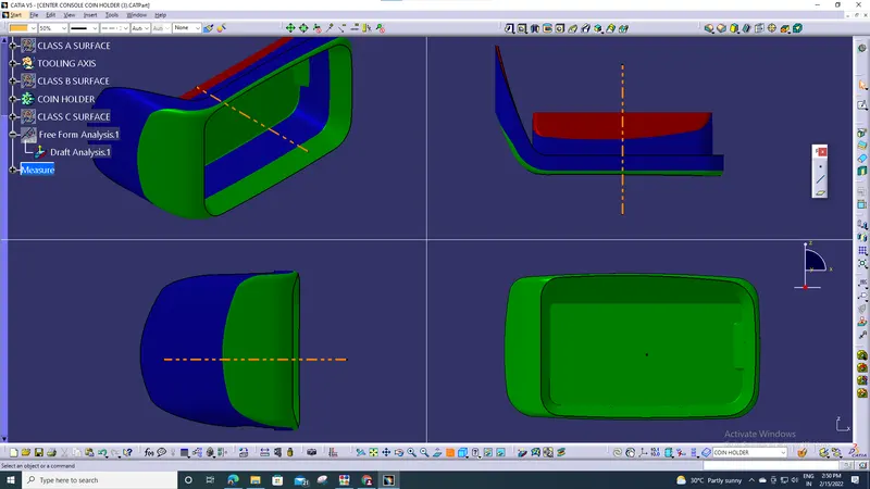
As if we observe here, there are no negative drafts at the opening side of the coin holder. Therefore, the designed part is suitable for manufacturing.
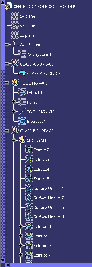
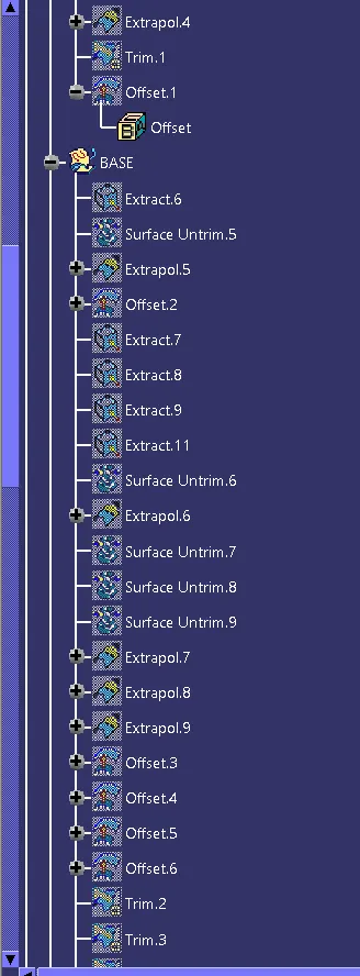
Tree Structure :
Conclusion :
The draft analysis is done on the given class A surface of the Coin holder, and it is found that the surfaces are having the minimum draft, and it is suitable for manufacturing. The class B and class C surfaces are created, and a solid part is created from the all surfaces.
THANK YOU