Week 8 - Challenge 4 - Coin Holder Design
DESIGN OF THE COIN HOLDER
A Coin holder is the interior part of the automotive. Here the main task is to design the coin holder using the Class A Surface and then finally perform the draft analysis in order to confirm that the design part can be manufactured or not.
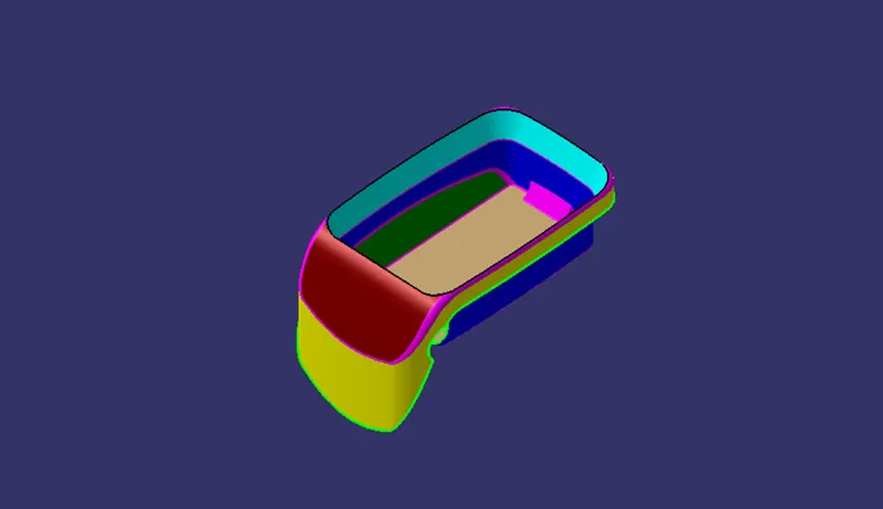
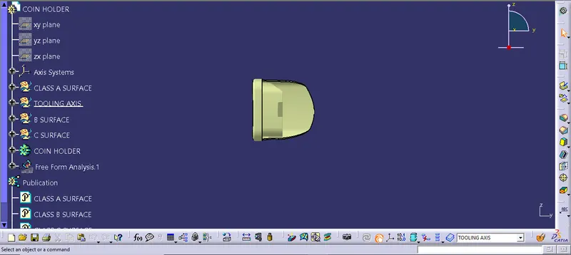
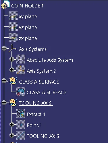
Now initially the Class A Surface of the coin holder is given as an input. So our first task is to find the tooling direction of the component. Now it is visually analyzed in all three direction X, Y and Z. The best tooling direction of the component is found out to be the Z direction. So here without intersecting any surfaces, the base is extracted and the point is generated on to it and the line is drawn perpendicular to it. The perpendicular line which we got is our tooling axis as shown in the figure below.
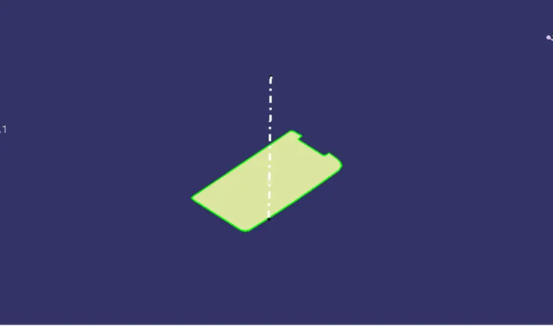
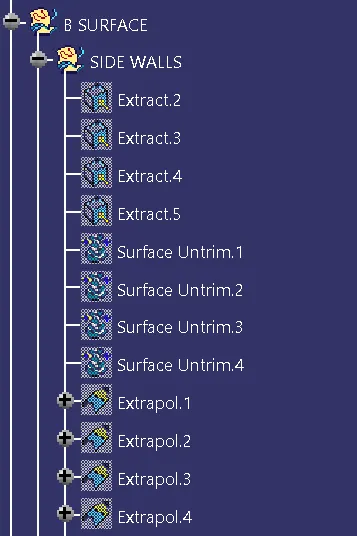
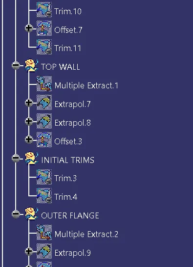
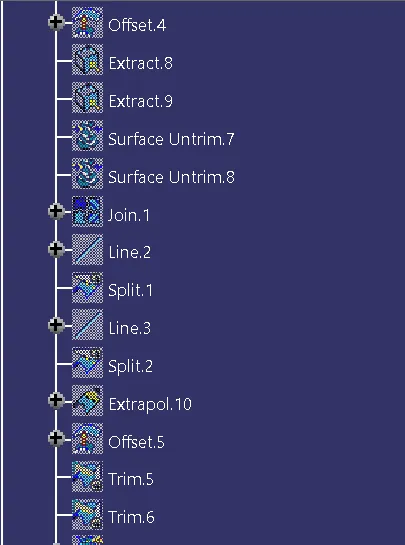
Now as the tooling direction is confirmed, the next task is to design the B-Class surface. In order to design the B-Class surface the patches are made and are given the different color. Patches in the sense all the wall surfaces of the coin holder are separated according to the design convenience. Now initially the inner wall are named as side walls by inserting the geometrical sets, then all the four surfaces are extracted one by one, then they are un-trimmed, after that they are extrapolated with no propagation and finally they are trimmed and are offset with thickness of 2.5mm.
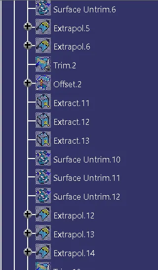
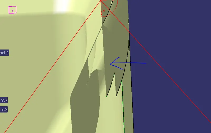
The same procedure is followed for all the parts of the B side surface. All the surfaces including base, top wall surfaces is designed in the same way as the side walls are designed. Finally the outer flanges is designed but this time they have given the offset on the inward direction as shown in the figure below. The arrow is showing the offset surface.
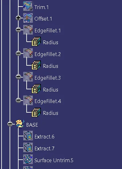
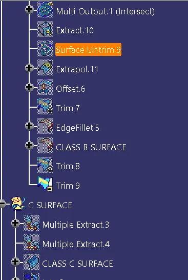
Now as all the surfaces are trimmed well and the fillet is provided the B Class Surface looks as shown in the figure below.
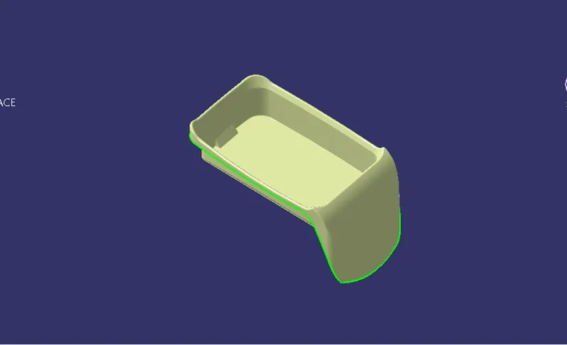
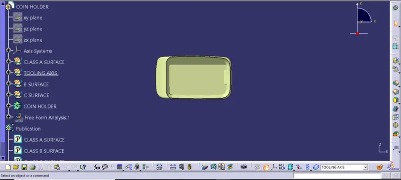
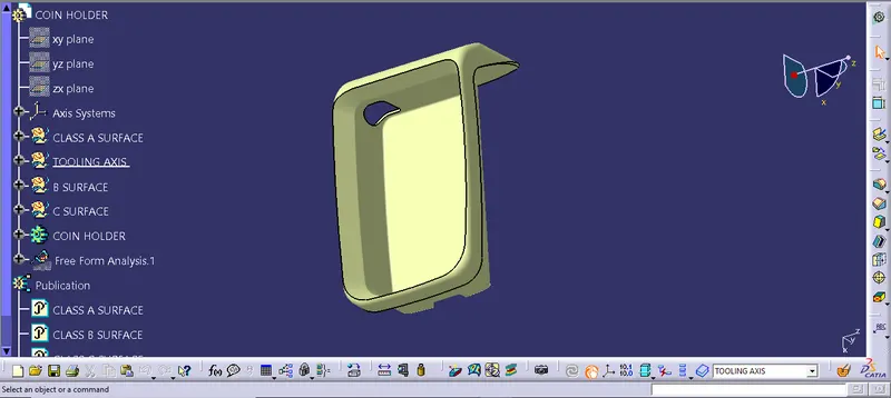
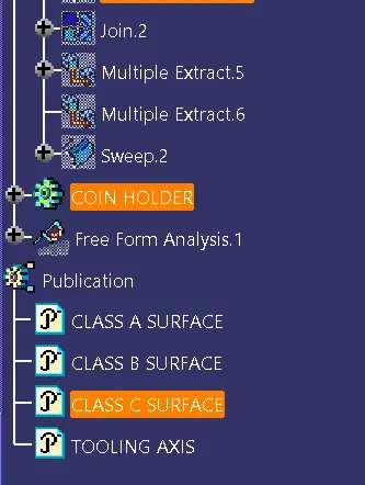
Now our Class B Surface is ready. Our next task is to create the Class C Surface which will be our joining surface between Class A and Class B Surface. So for the Class C Surface initially the boundary is extracted of the Class A Surface. Now here the Class C is to be made perpendicular to the Class A Surface. Hence the sweep with the reference surface command is used to create the C Surface. Then the Class B and C Surface is trimmed together and is finally joined and trimmed with Class A Surface. Now finally the inner rectangular block is extracted, untrimmed, extrapolated and trimmed with the earlier base surface and then it is finally replaced with the initial extracted base surface. And then fillet of 1mm is given to the rectangular block. Hence our component is completely designed as shown in the figure below.
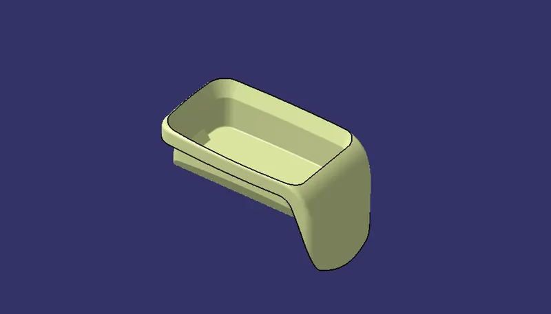
Now the part body is defined and the part body section is opened from mechanical design option and then the closed body command is used to create the whole body into the solid component as shown in the figure below.
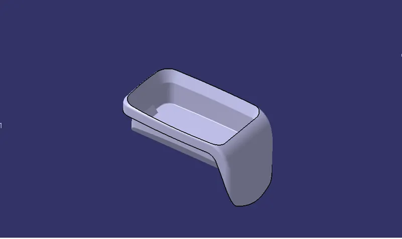
Now as we have the solid body so finally the draft analysis is to be done to find out the above designed product can be manufactured or not.
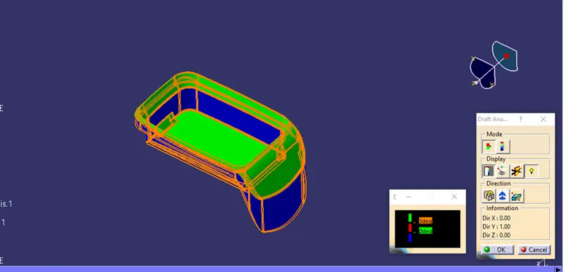
In the draft analysis initially the compass is kept on to the tooling axis then the body of the component is selected which tells us the draft angle of the component if the angle is less than 3 then double click the value and add 3deg to it. But now also some of the inner faces of the component is showing the negative draft but actually when we measure the draft angle of those faces using the analyze under running point command so it shows the value less than 3deg but not in negative, so it can be ignored. The figure is shown below.
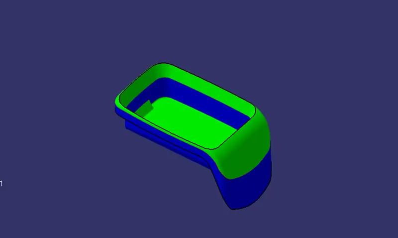
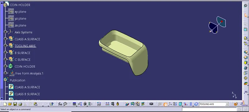
Hence our coin holder is designed and also the draft analysis is done which ensures that this product can be manufactured.
IMAGES :-