Week 8 - Challenge 4 - Coin Holder Design
DESIGN OF COIN HOLDER
Objectives:
- To define a tooling axis for the class A part surface given.
- To model the Class B, class C surfaces using surface commands
- To make a completely solid body from surfaces
- To Conduct draft analysis on the solid part
Software used: DS CATIA P3 V5- GENERATIVE SHAPE DESIGN, PART DESIGN WORKBENCH
Introduction: A class A surface patch of a coin holder is provided for this assignment. The goal is to make the thickened part to be manufactured in 3d using CATIA. we can use the same method of offsetting surfaces for this project also. however, the element does not have a given draft angle in class A. and the class C surfaces are coming in perpendicular to the tooling axis.
Design methodology/ Approach:
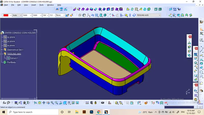
Given part:
Step 1: Tooling axis generation:
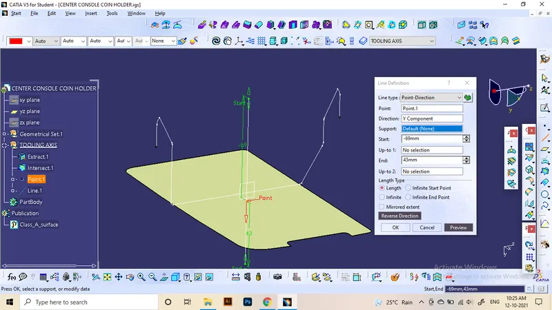
In this specific part, sidewalls of the given Class-A surface are parallel to the z-axis direction. There isn't provided a draft angle. So that the tooling axis does not needs to be made using the bisecting method. The tooling axis comes exactly at the middle of the base at z-direction.
Step 2: Class B surface generation:
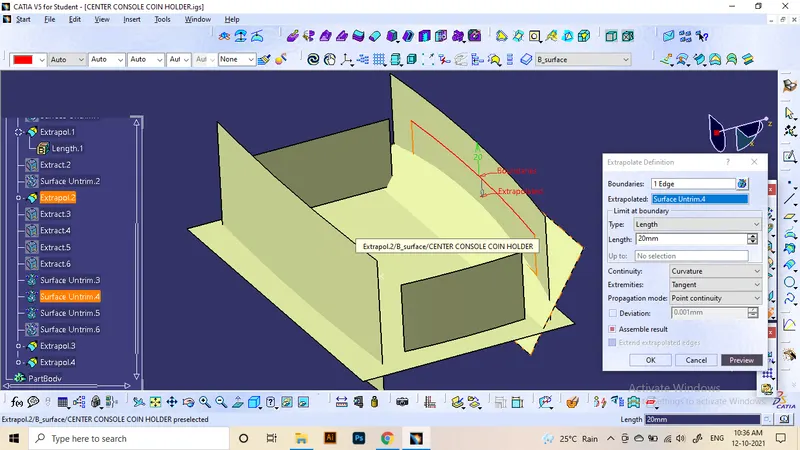
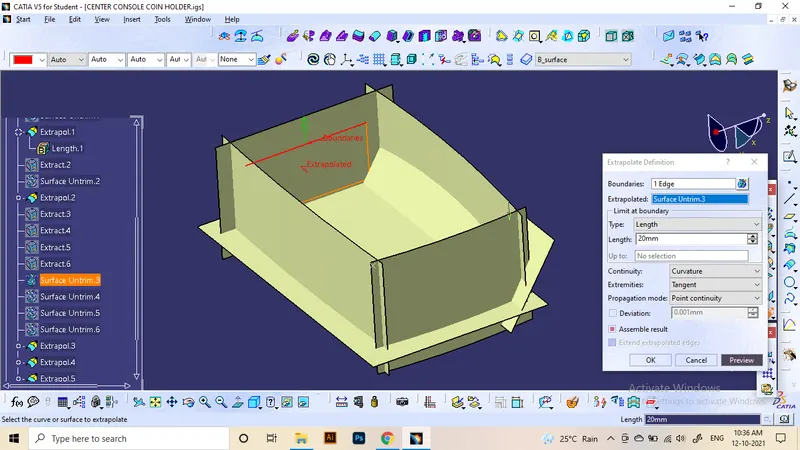
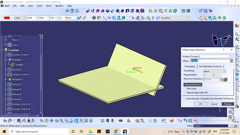
All required surfaces from the class A part will be extracted and extrapolated as shown for generating the surfaces for the class B, starting from the base. these surfaces will be offset to their specific direction at the distance equal to the thickness of the part, ie 2.5 mm
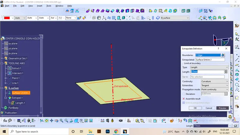
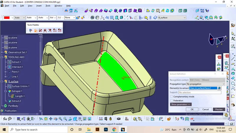
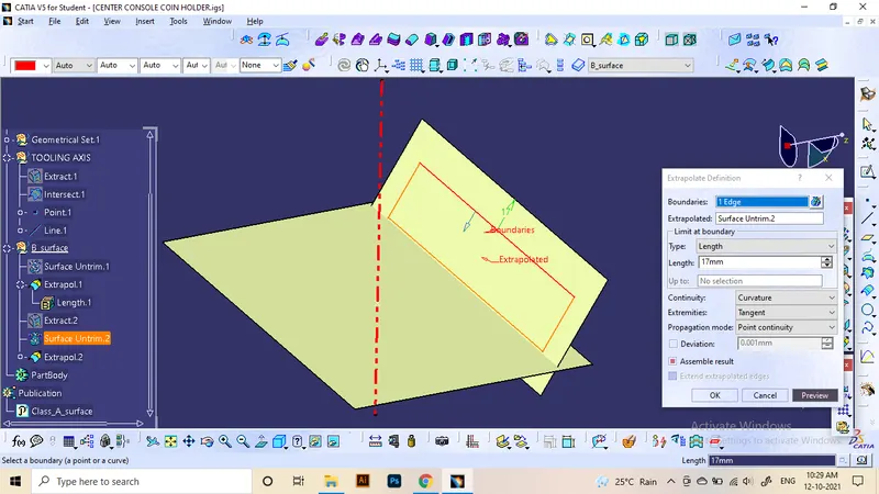
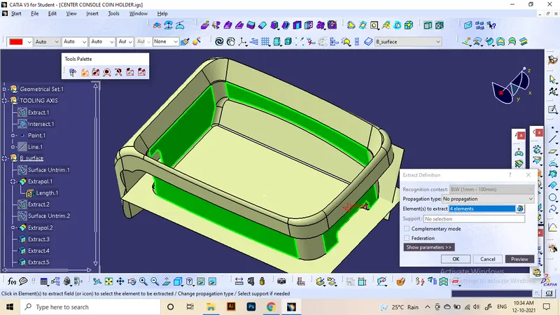
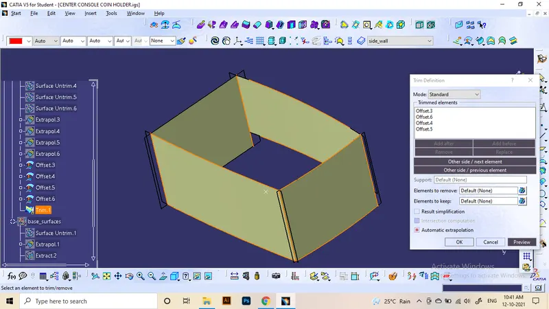
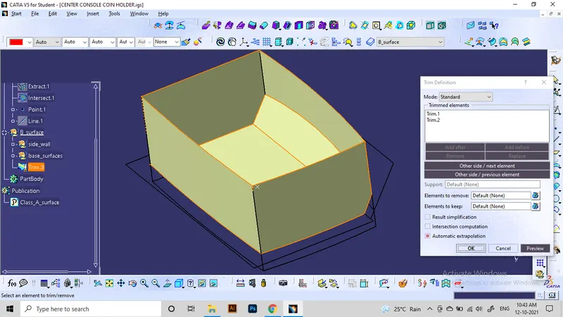
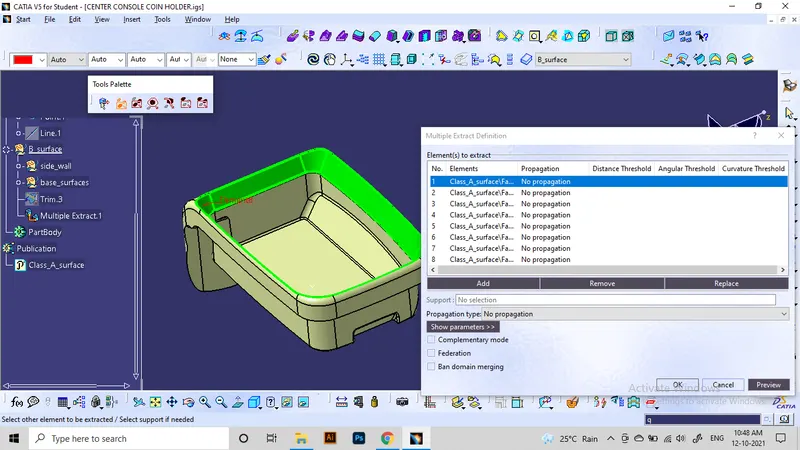
Top wall surfaces can be extracted as a single patch and offseted at once due to it's continous manner.
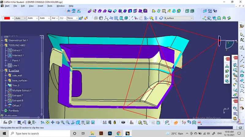
Using section views to check for the thickness.
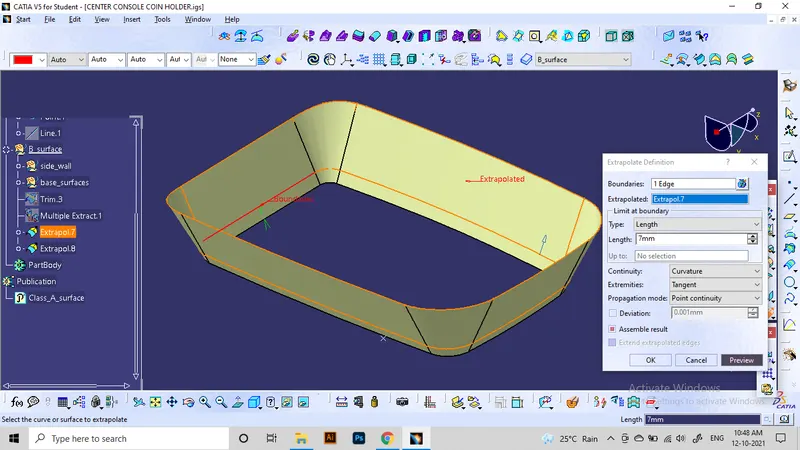
The main wall surfaces have different fillet values. All of them are measured initially, for applying the fillets to class b surface, the value of wall thickness is either added or subtracted from the fillet values of class A according to the type of fillets.
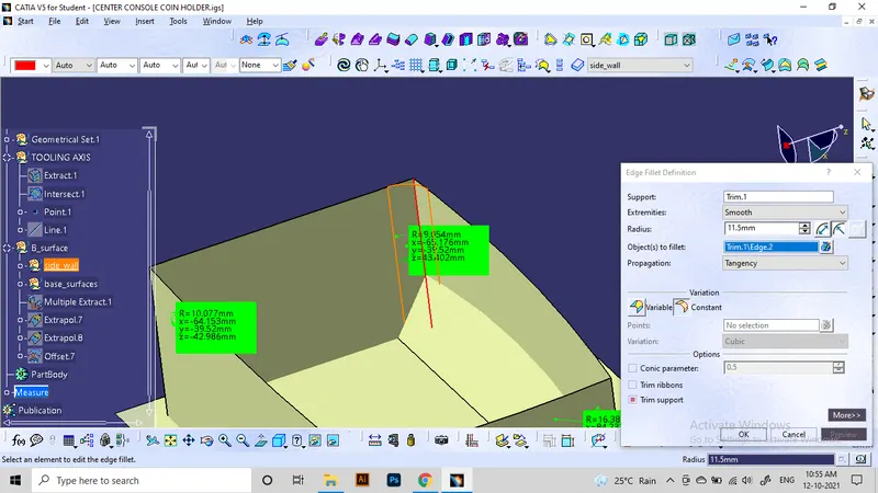
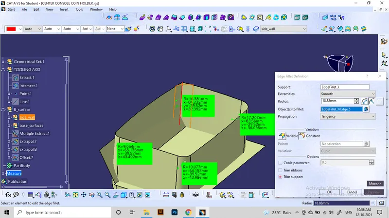
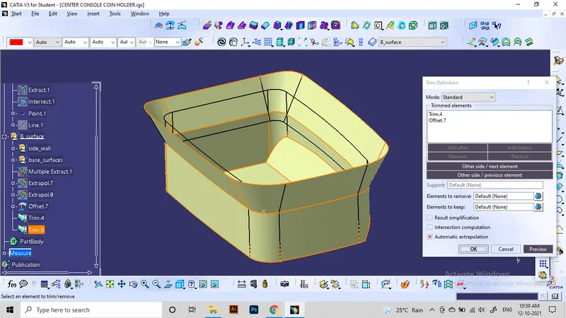
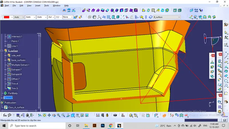
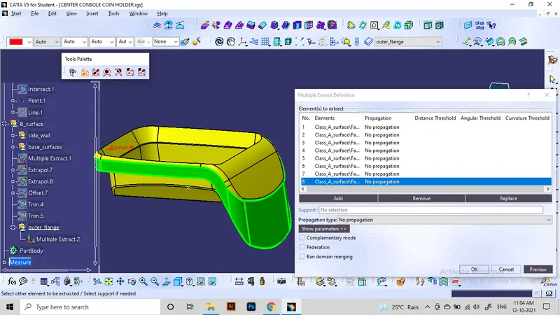
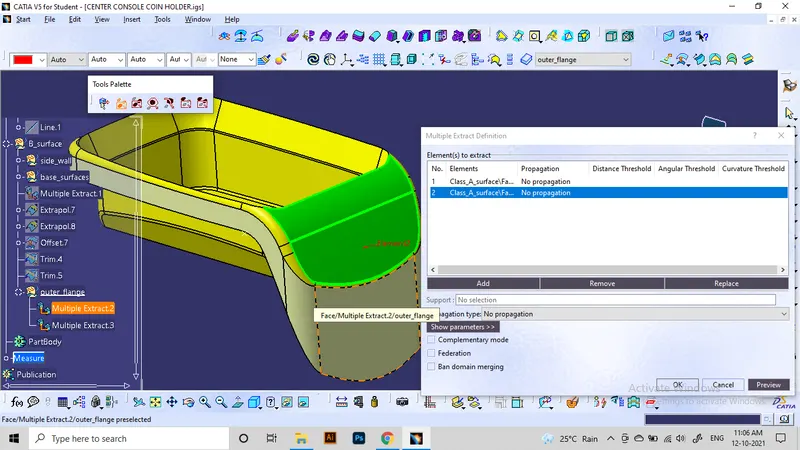
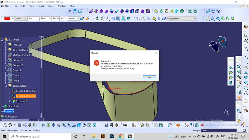
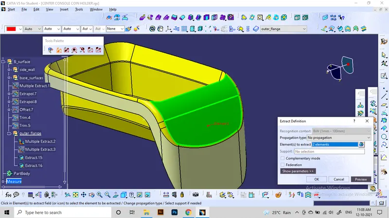
The upper part of the flange cannot be extrapolated directly. So we need to extract them individually and untrim and rejoin again to be able to extrapolate the patch.
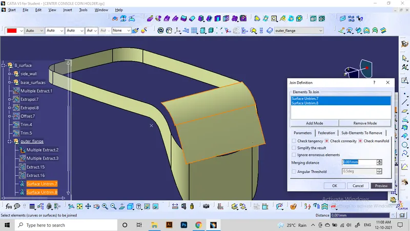
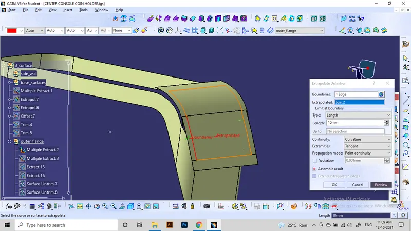
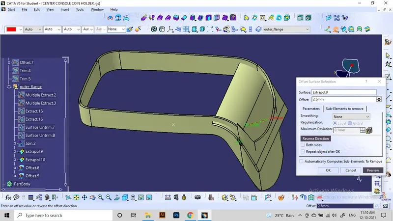
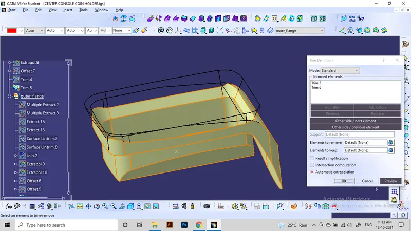
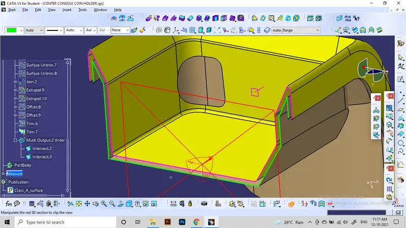
Here it is marked the pink line for class A and green for class B. the surfaces are proper and have equal wall thickness. edges of class B will be filleted later.
Step 3: Class C surface generation.
Here, the bondary edges is extracted for sweeping the class c surface. From the above image, it is clear that, the c surface which connects class A and class C, comes perpendicular to the tooling axis.
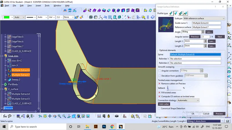
So the sweeping option suitable here is the 'with reference surface' option. The class A surface which in contact with the boundary will be the reference surface and the angle is 90 degree.
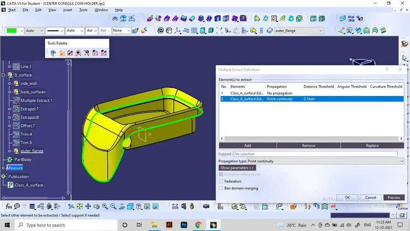

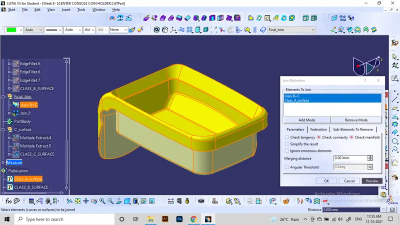
Also the edges of hole inside the part needs to swept similarly to make patch for the class C. these patches will be trimmed with class B and joined together with class A to make final assembly.
Step 4: Final patch generation.
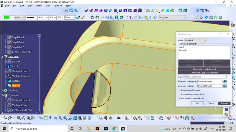
After the trimming and joining the final patch is generated. Checking for any missing parts or fillets.
A small surface is there on the inside of class A which also needs to thicken, Here we can edit the base surface trim by including the offseted surfaces of that part and i use local update option to update that into the final element.
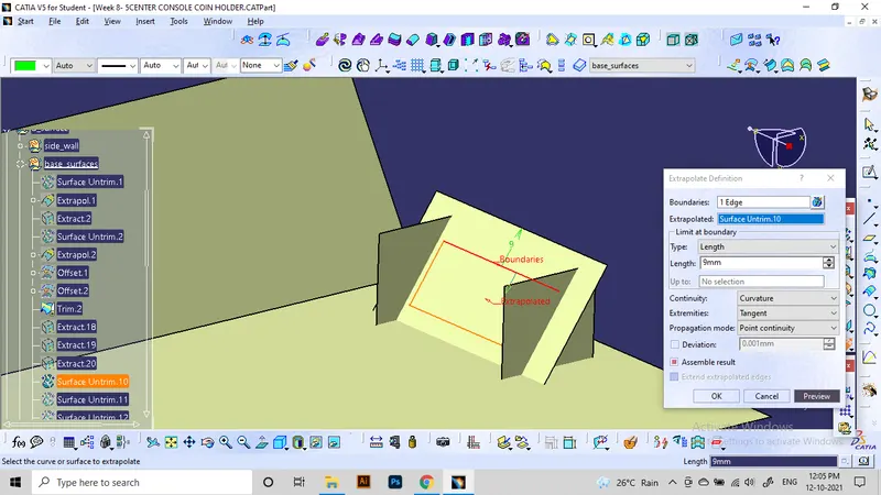
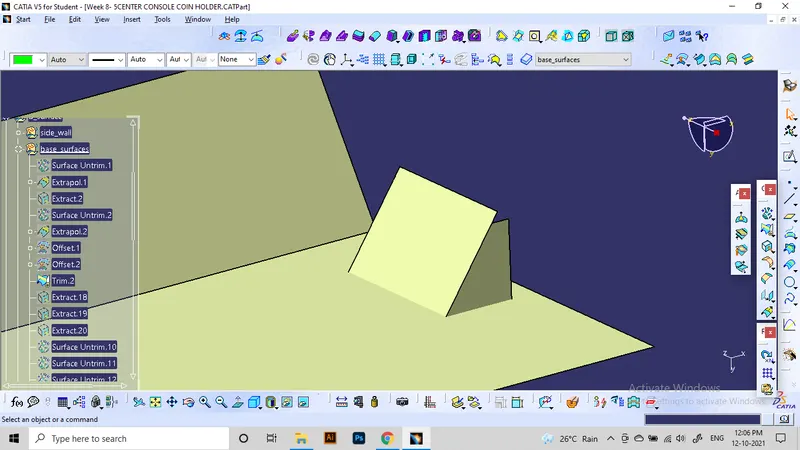
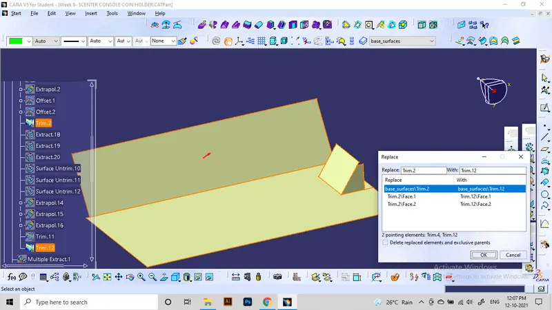
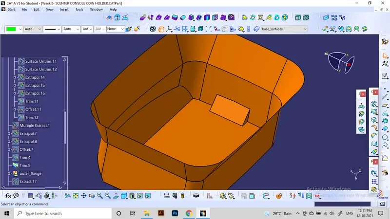
Here is the modified details are shown using section view.
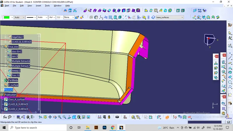
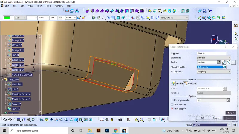
Here is the completed surface product without any boundaries.
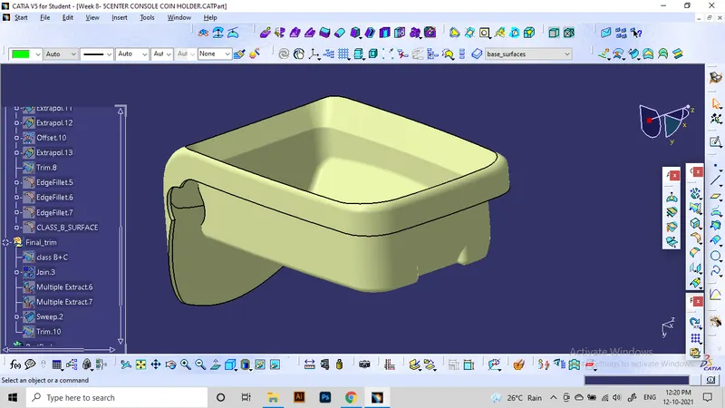
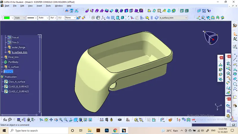
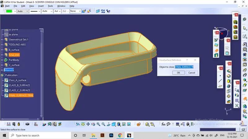
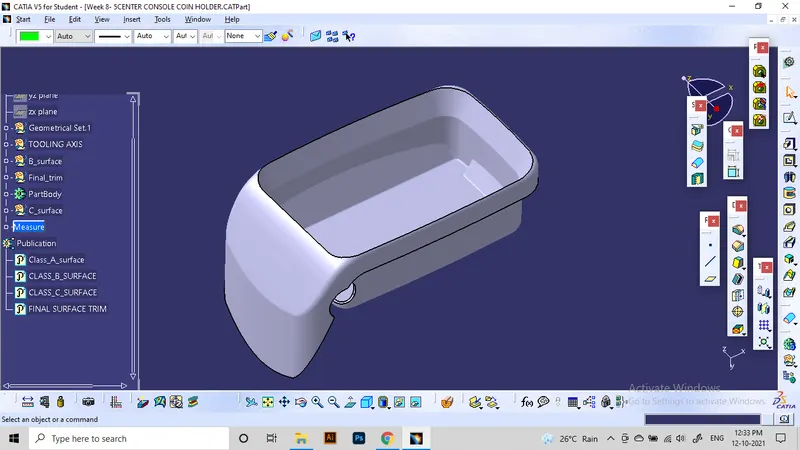
Step 5: solid part creation
Step 6: Draft analysis:
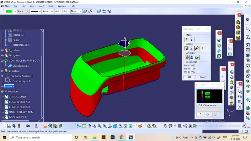
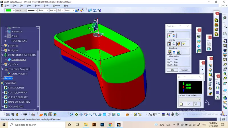
Here attaching the results of the draft analysis in the direction of the tooling axis.
Sidewall surfaces are generated at a draft angle between 0 to 3 degrees.