Week 8 - Challenge 4 - Coin Holder Design
AIM:
Creating the coin holder plastic component through the A-class surface and add thickness to it
Objective:
- Creating the B and C surface
- Creating the tooling axis
- Performing the draft analysis on both A surface and final plastic components.
- Take the Thickness of the component to be 2.5 mm
Introduction:
The input of the product designer is in the form of the A-class surface. The job of the product designer is to create the B and C surfaces keeping all the aspects for the mold.
Class A is
- Visible surface and aesthetic look
- surface with textures
- Surfaces provided by customer (OEM)
- Don't have any features like (rib, snap, bosses, etc.) on class A surface.
- Class A surface is made from scanned data with different software like alias etc.
- Surfaces which are having CURVATURE CONTINUITY IS CALLED class-A.
Steps to produce b surface
- Make sure the boundaries are clear.
- Now you may start making the tooling axis.
- The tooling direction is used to determine which way the part is ejected from the mold or which way the core and cavity are moved before the part is ejected.
- To make the part easier to manufacture, the draft on the part should be positive. In relation to the tooling direction, the draft angle should be positive.
- To establish the tooling axis, we'll need the correct orientation or view, which shows the component's correct features and draft.
- To obtain the boundary lines, use the intersect in the ZY plane. The lines are then drawn along the slanted surfaces.
- Here, the wall lines and the base form a zero-degree angle. As a result, the final tooling axis will be perpendicular to the base or pointing y from the Centre point.
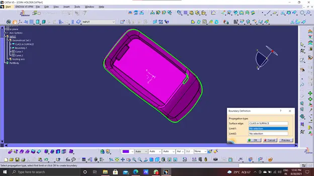
- In this case, the component view from the Y-axis provides the tool with the right view to see the features existing in the geometry.
- The tooling axis from the other direction, which gives the wall draft angle, is required to generate the tooling axis from the Y direction.
- The coin holder's initial tooling axis will be the bin base center.
- The tooling axis that resulted from the preceding steps
- The basic layer is removed.
- Then, using the point on the surface at O, the center point is formed.
- The axis system is created at the point where it is created.
- After that, change the model's view to the X axis and create the tooling axis.
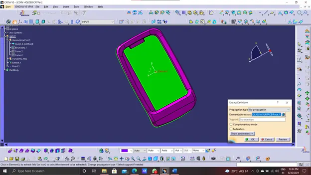
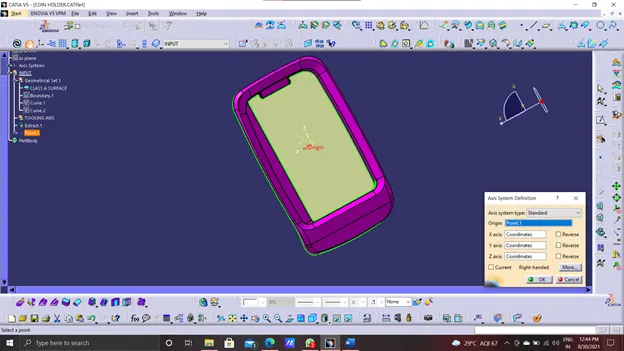
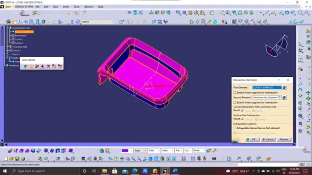
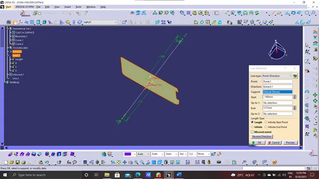
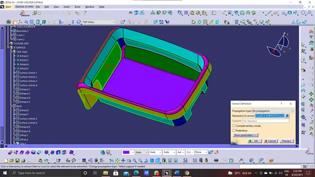
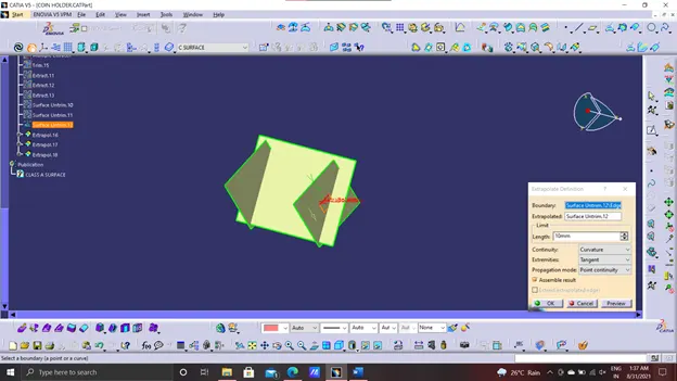
- First, extract all 4 surfaces of the sidewall of the coin holder. Then these surfaces are first untrimmed to get the intersection for surfaces so that a replica can be created.
- If the surfaces are not intersected, then extrapolate by point continuity propagation is used to make these surfaces have an intersection between them.
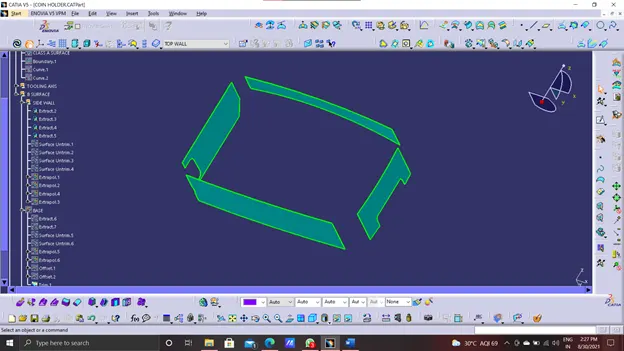
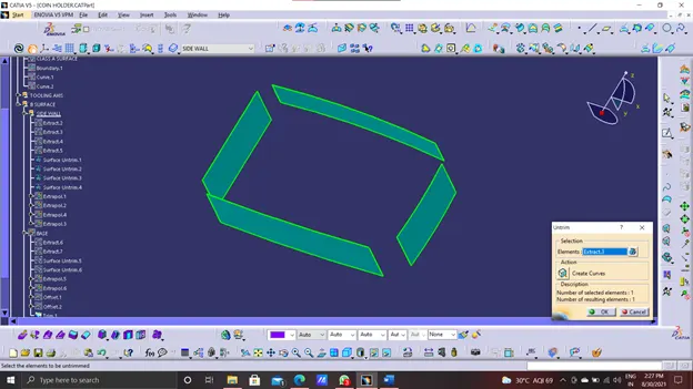
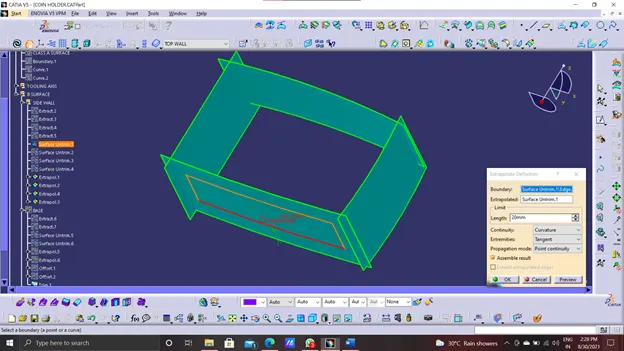
- Lastly, the surface trim is used to get the replica for the inclined surface.
- Now extract the base surface and base side wall.
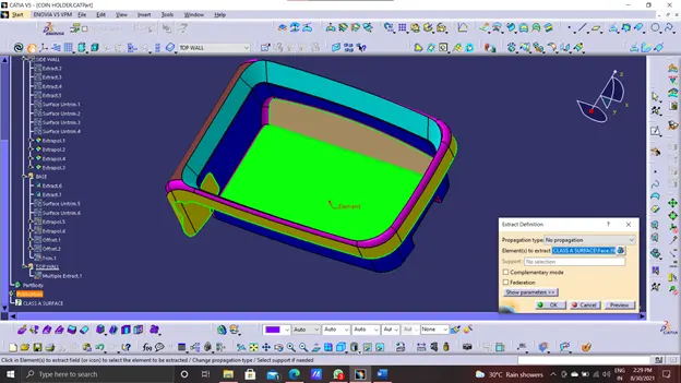
- Untrim the surface.
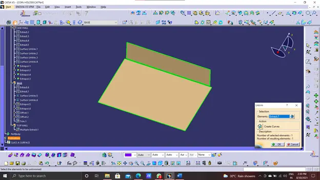
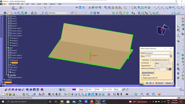
- Now extrapolate the surfaces.
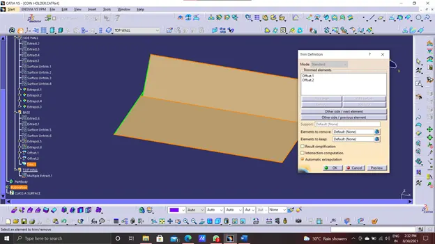
- Now trim it
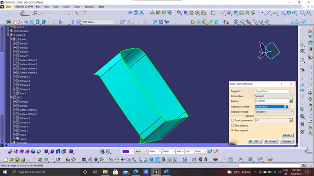
- Now edge fillet the sidewalls.
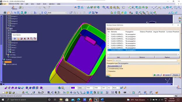
- Now use multiple extract in upper wall surface.
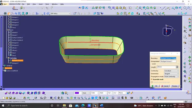
- Now extrapolate the multiple extract surface.
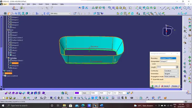
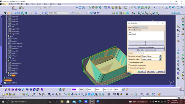
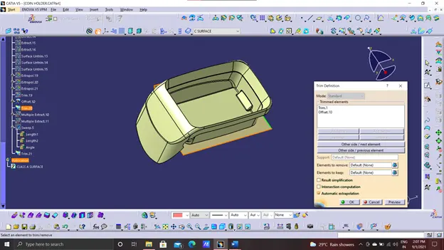
- Now trim the sidewall surface with base surface.
- Now offset the upper wall extract by 2.5 mm.
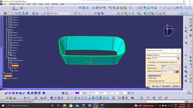
- Now trim the upper side walls.
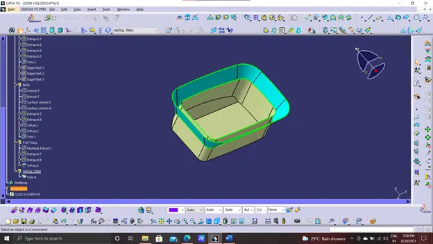
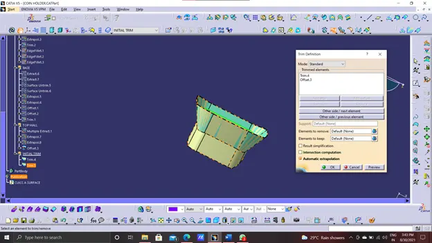
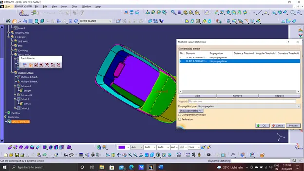
- Now use multiple extract for the outer flange.
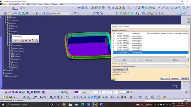
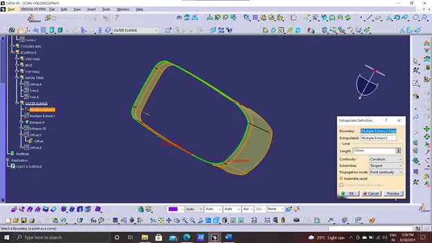
- Extrapolate the surfaces.
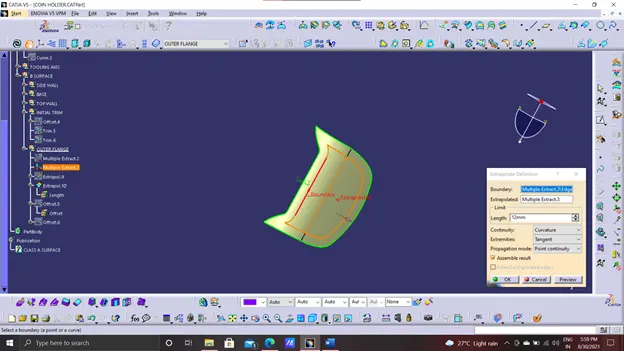
- Split the surfaces as shown.
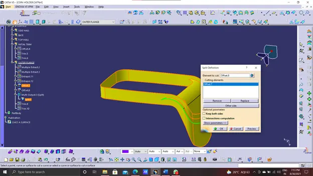
- Now trim the outer flange and the trim.
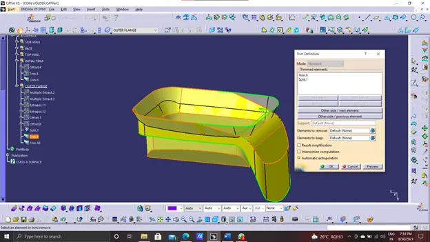

CRAETING C SURFACE
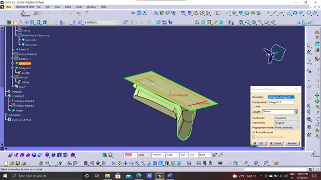
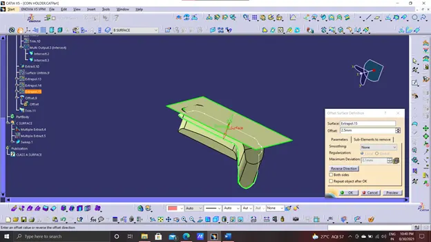
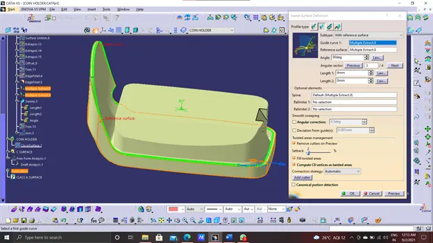
- Sweep the boundary of outer flange.
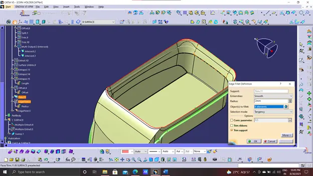
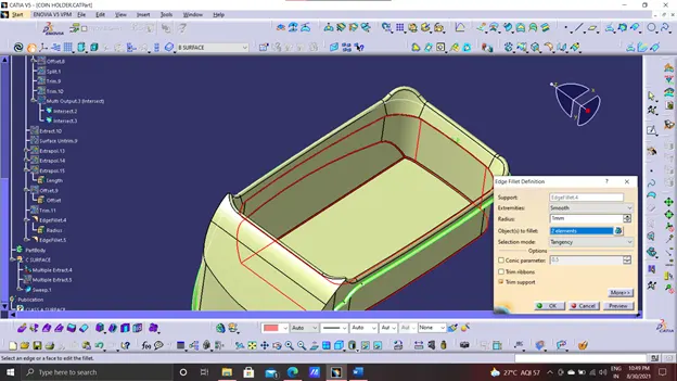
- Edge filet the sharp edges of upper walls and outer flange.
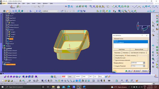
- Now trim the class A surface and the trimmed surface.
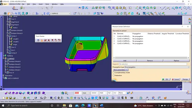
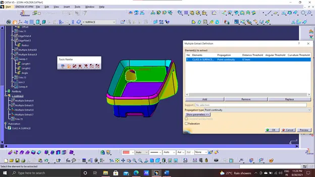
- Now extract the edge of the cut portion and then sweep it.
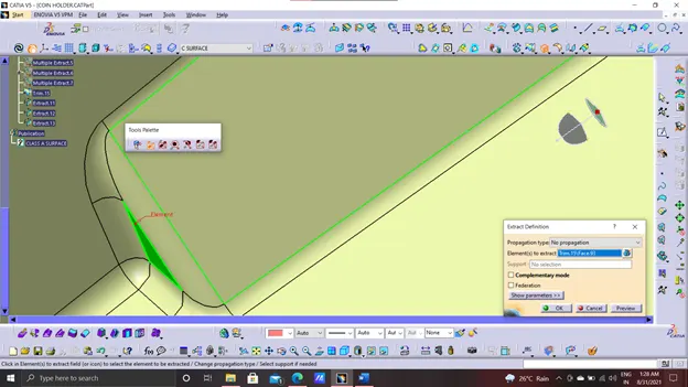
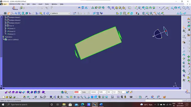
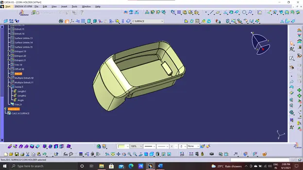
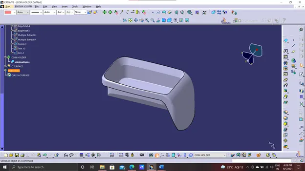
- Now convert the class C surface in solid part body.
Draft analysis:
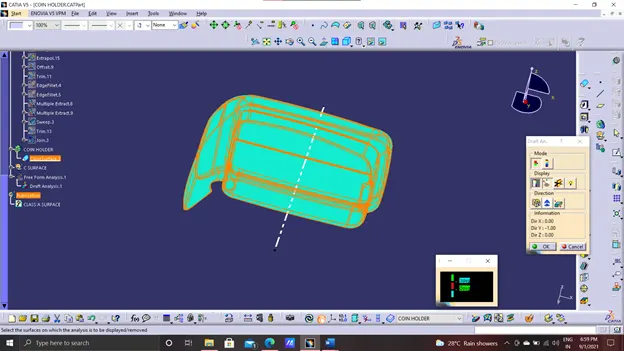
- The view parameters are initially set to material mode in order to do the draft analysis.
- Then go to Insert and choose the feature draft analysis option.
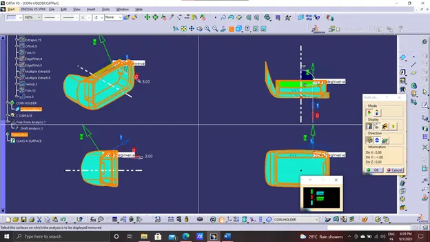
- To begin, choose the axis system and drag it to align and coincide with the tooling axis, then lock the orientation. According to the tooling axis, this axis system determines the draft direction.
- Set the minimum draft value and turn on the colour scale. It's set at 3 degrees here, and it'll be displayed in green. Any draft angle less than 0 degrees will be highlighted in red.
- Select the running point tool to measure the draft angle at various points, and then pass the draft analysis if all surfaces pass. If the component has the required draft angle, turn on the light effect, which will show the component in green colour.
- The final draft analysis shows that the draft angle on the green colour surface is greater than 3 degrees, whereas the draft angle on the red or cyan colour surface is less than 0 degrees.
- The red colour surface, which is a negative draft, cannot be ejected or created using the main tooling axis.
- The alternative is to create a new tooling axis that catches all of the remaining surfaces, but this is not practical. The only option is to make adjustments to the A-class surface.