Week 8 - Challenge 4 - Coin Holder Design
CENTRE CONSOLE COIN HOLDER
AIM: To create centre console coin holder plastic component through the given class-A surface and to perform the draft analysis on the final model of the coin holder and also for the given class-A surface.
CENTRE CONSOLE COIN HOLDER: A coin holder is a plastic component in an automotive vehicle where all the coins and all small size stuff can be placed.
Steps for the creation of centre console coin holder as a solid part are as follows:
Here we are provided with the class-A surface of a coin holder and from that we have to create class-B & class-C surface for coin holder.
Step 1. : Creation of tooling axis
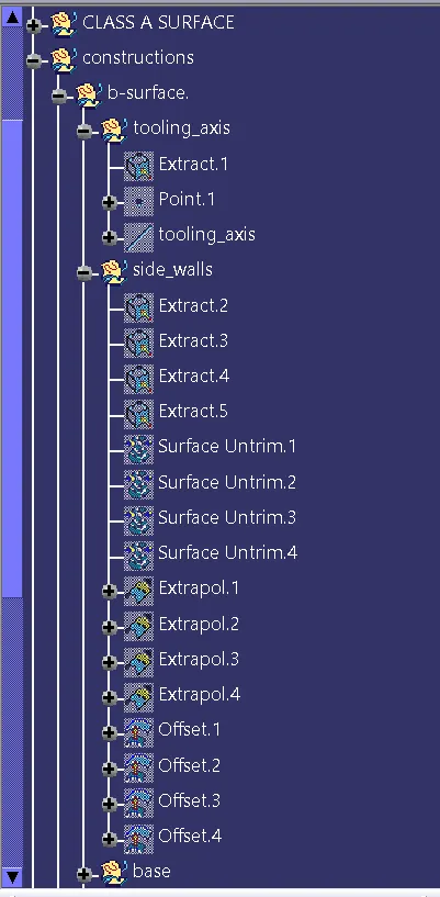
- Initially we made all the proper geometrical sets after doing the visualisation check for the given class-A surface and identifying the how many parts to be designed.
Judgement made for making the tooling axis:
- Then we found that there was a bin inside and that was our major priority for the tooling axis to be made and all the surfaces can be cleared if we made a tooling axis normal to the bin surface in centre.
- Also we found that the walls are exact 90 degree to the base of bin surface, so the tooling axis can be made normal to the base surface at the centre.
Steps for the creation of tooling axis
- Initially we extracted the base surface and created a point in the middle of the surface.
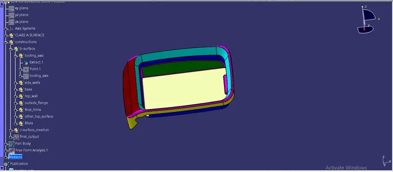
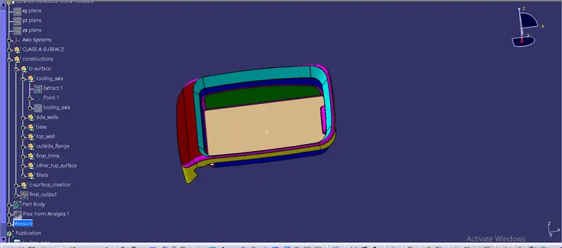
- Then we created a line normal to the surface with a point as a referance point. And that was our main tooling which was clearing all the surfaces but in some areas there were deviations while we took a draft analysis.
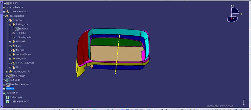
- Then we took a class-A surface and toolling axis in a publication and later we do the draft analysis with respect to the tooling axis.
Step 2. : Performance of draft analysis on a class-A surface
- Click on draft analysis command and place the compass properly on the the tooling axis ensuring that it is proprly lying on the tooling axis.
- Click on class-A surface and adjust the compass accordingly that they must clear all the surfaces and lock the orientation or position of the compass and then click ok.
- Ensuring the draft angle is given as 3 degree.
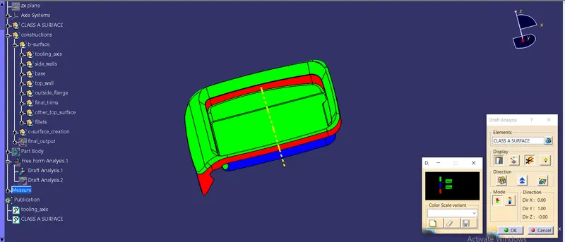
Note: When we do the draft analysis on a class-A surface we found that some areas are not clearing by the tooling axis even after changing the draft angle to 3 degree or changing the direction of the compass. This is because the given class-A surface has no draft angle in some areas also as we had discussed earlier that the wals are normal to the base so it is not clearing some surfaces which are normal.
Step 3. : Creation of class-B surface
Creation of class-B surface involves many different geometrical sets for different parts as we had divided it into 5 different parts. Class-B surface is made by extracting the class-A surface and performing related operations on it and ensuring to offset it as we had to add the thickness of 2.5mm so we have to offset each of the surface which we are extracting by 2.5mm. The offset direction for creating a class-B surface is in outward direction for the base, walls & top walls and for the outside flange it is inward direction because as the visible area is only class-A surface, So their creation process are as follows:
Step 3.1: Side walls
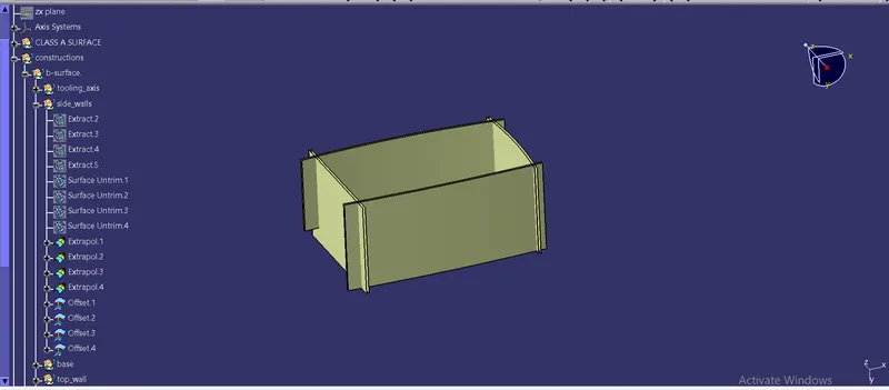
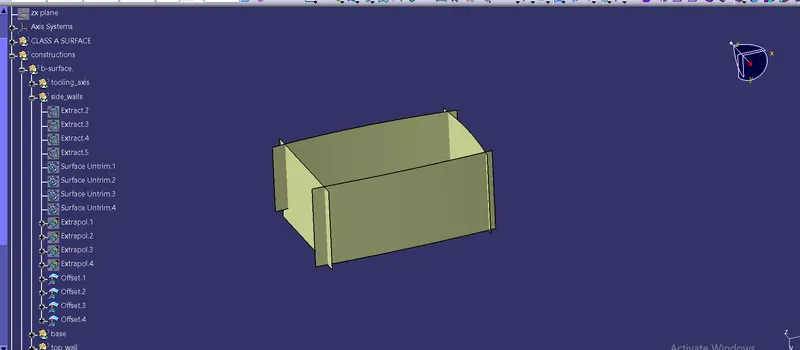
- Initially we extract the side walls and later we untrim all the extracted surfaces and extrapolate all one by one ensuring all the surfaces are intersecting each other and there will be no gap between them.
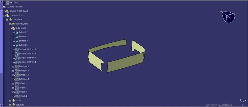
- Hiding the parent is advicable after extracting the surfaces for further untrimming.
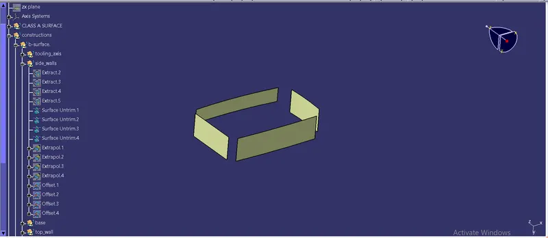
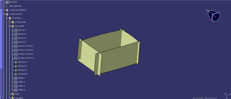
- After extrapolating the surfaces we need to offset all those and ensuring we hide all the extrapolates after offseting the surfaces.
Step 3.2: Base
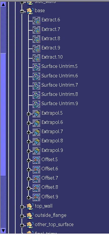
- While extracting base surface we consider the side surface and small triangular surface which is attached to the base as a single base surface.
- Again we extracted these surfaces and later we untrim them all and extrapolated very well so that they all intersect with each other.
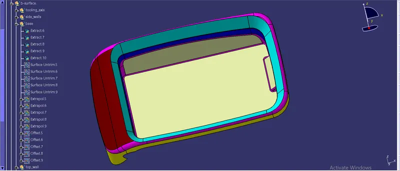
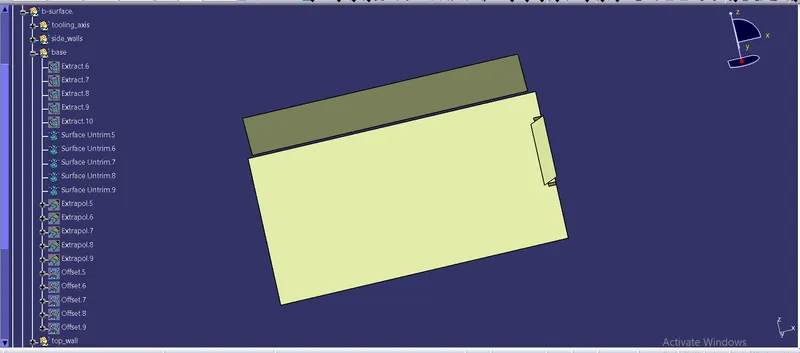
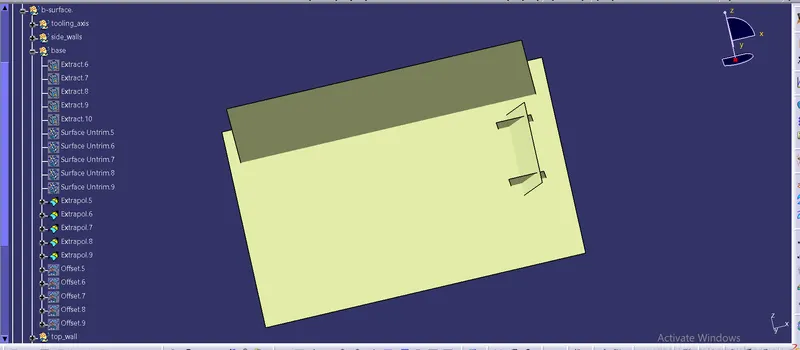
- We make sure that all the surfaces are offsetted outside direction after doin the extrapolation process. This can be done by checking with the class-A surface.
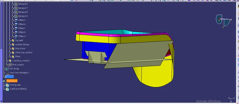
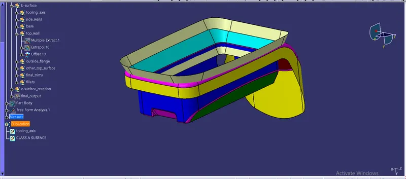
Step 3.3: Top wall
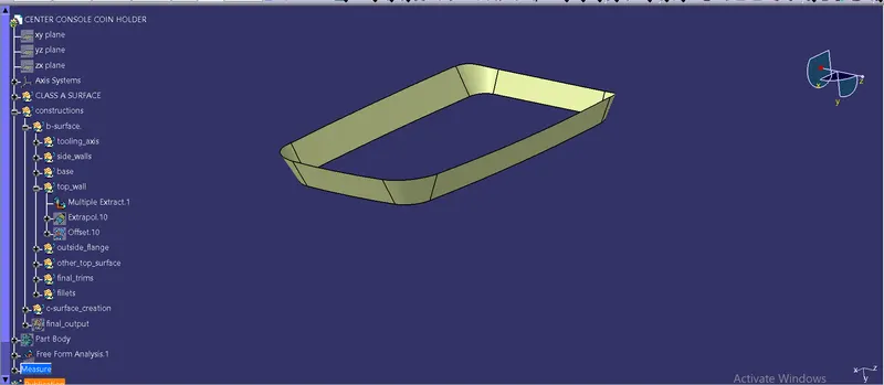
Note: For creating the top wall we can extract all the top wall surfaces with the edges on it because it is final most surface, and we dont need to extrqct it one by one and then do the fillet operation. This leads to the expansion of tree structure. But after creating the top wall we need to trim them together with the base and side wall, so there may be problem if we are not filleting the side wall before trimming them together. Because there are two fillets one on the top walll and one on the side wall also. So the fillets may create a problem. So it is advicable to do the filleting operation in the middle if necessary.
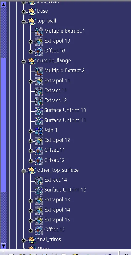
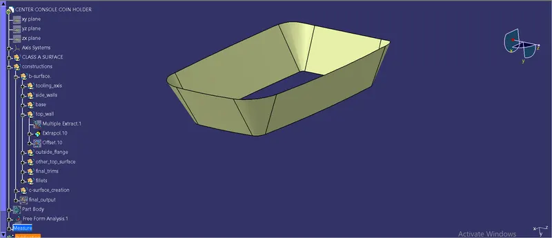
- So we create complete extract of the top wall and for that multiple extract is the best command with no propogation.
- Then we extrapolate the upper and lower edges to an appropriate value.
- Later we offsetted it in the outside direction.
Step 3.4: Outside Flange
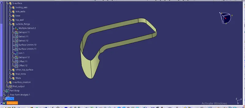
Note: For creating the outside flange we have two surfaces to be extractedone is outside covering all the top wall and side wall and one is at top. So we need to extract it separately. And we need to offset those extracted surfaces in inside direction as the class-A must be always on the top side and must be only visible.
- We extracted the outside surface of the outside flange first and extrapolate the uppper edge only as the lower edge is the lowest surface so we dont extrapolate the lower edge and done the extrapolation on the upper edge by minimal value so that intersect with the outside top surface of ouside flange.
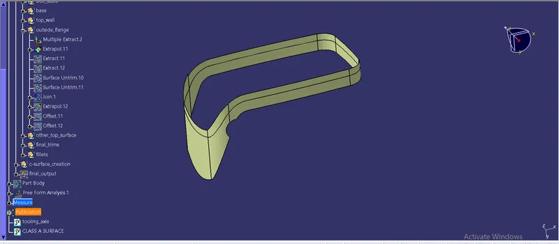
- Then we extract the ouside top surface but while extrapolating that surface we found that it is not extrapolating, so we extracted both the surfaces separately and then untrim them and later join the untrimmed surfaces together.
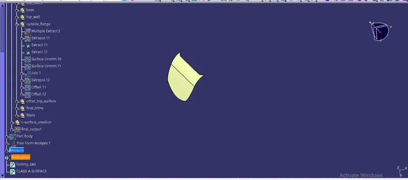
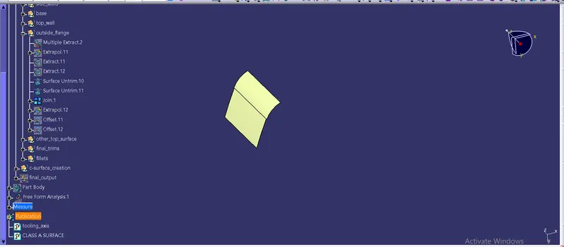
- And now we extrapolate these join surfaces with the point contuinity command to intersect into the outside surface.
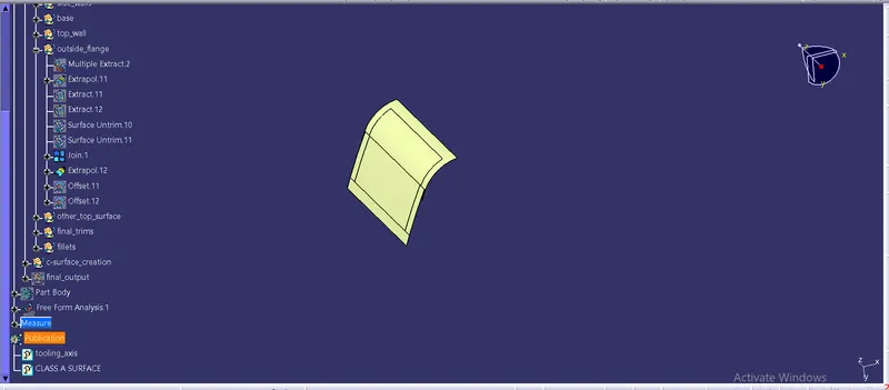
- And we offsetted both the surfaces i.e, outside & outside top surface to the inside direction by 2.5mm.
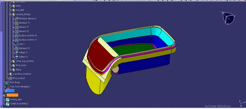
Step 3.5: Other outside surface
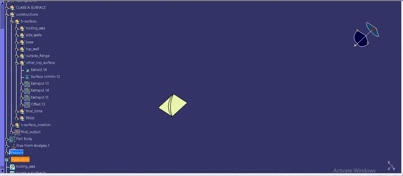
- By observing closely to the class-A surface we found that a flat surface is cutting the top wall, so we need to extract that also and later untrim it extrapolate it very well throghout the model.
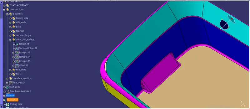
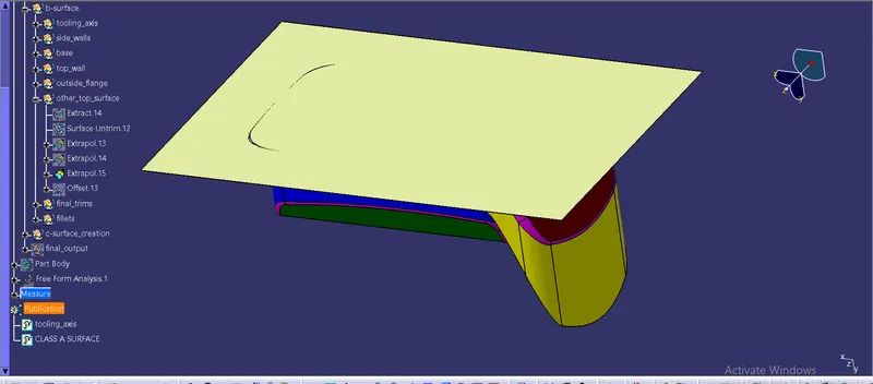
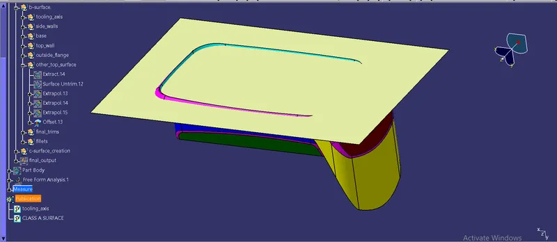
- We may need to extrapolate two times all the edges to cover all edges of class-A surface. We might not know weather it is intersecting at any other point.
- Later as it surface of class-A so we need to offset it in downward direction below the class-A surface. As our class-B surface is made under the class-A surface so offset must be in the downwrd direction.
Step 3.6: Final Trims
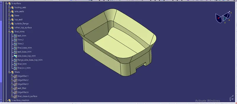
Note: Once all the surfaces are created, we need to do the trimming between all the offseted surfaces. Here we may also go with the filleting in middle after performing the trims. Because some surfaces may lead to degeneeration after performing all the trim operation and then going with the fillets. Here some surfaces are trimmed with the filletted surface also.
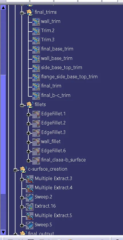
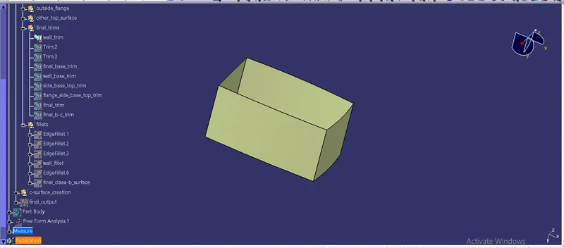
- Wall Trim
- Final Base Trim : Here we did the trim of side base with base surface first and then do the trim of small triangular portion and later trimmed with obtained trim and hence got the final base trim.
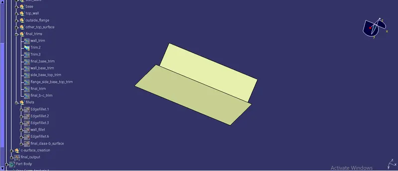
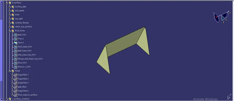
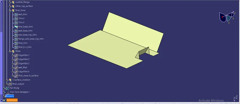
- Wall Base Trim : Here we did the trim of side wall with the final base. Here we filleted the side wall trim first and then we did the trim of side wall and final base trim.
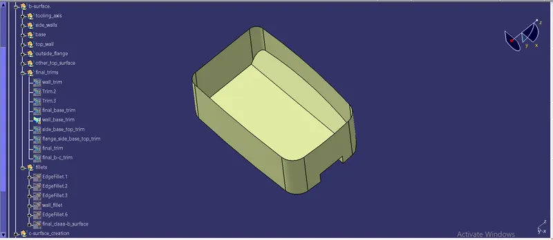
- Side-Base-Top-Trim : Here we trimmed the obtained trim of side wall and base with the top wall. Here we might got degenerated surface formation of trim if we do the trims first and then fillet all. Hence we did the fillet at first only.
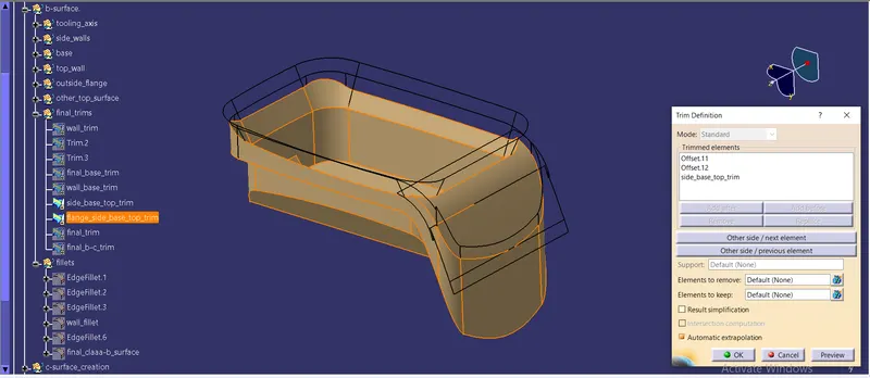
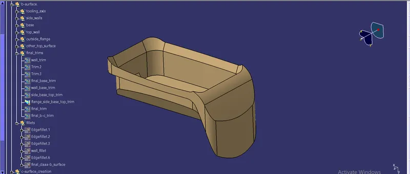
- Flange-Side-Base-Top-Trim : Here we did the trim of outside flange, outside top flange and the obtained trim of walls and base. We may do it in different trims but we did it in a single go.
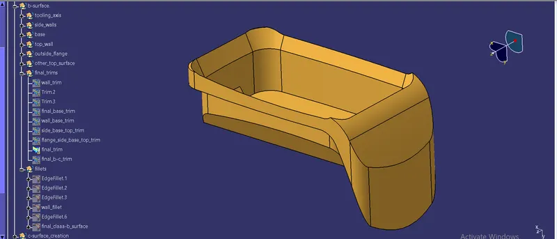
- Final Trim : Here we did the final trim of obtained trim with flat surface on top wall.
Step 3.7: Fillets
- Fillets are done in middle of the trims to avoid the unwanted surface creation of the model. Here we had arranged the fillets in a different geometrical set and done it after the necessary trimming of the surface.
- For the fillet operation we need to measure the fillets on the clsas-A surfaceand this can be done by keeping all the measures in a tree itself and can be seen even after hiding the class-A surface.
- Initially we done a trim on the side walls in the earlier stages when we had not trimmed it with any other surfaces of the model.
- As the fillet values for every corner of the side walls were different so we did it in a single-single fillet operation and finally got a final side wall trim.
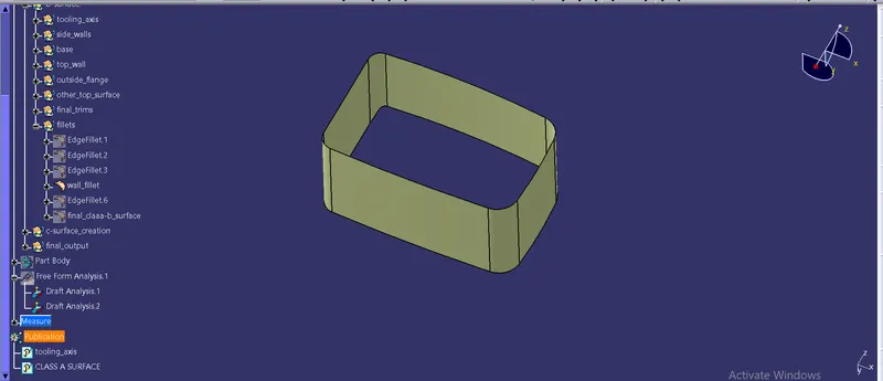
Note: As we are creating the fillets on the class-B surface, we are adviced to ensure that whenever the fillets are made on the class-B surface which is below or inside the class-A surface we reduce the thickness value from the fillet value, and adding the thickness value to the fillet value in the case of fillets to be given outside the class-A surface.
- Here the fillet value for the side wall is given by adding the thickness value to it as the side walls of class-B surface are outside the class-A surface.
- Later we gave the fillet value for the final class-B surface and again these surfaces are inside the class-A surface so we reduce the thickness value from the fillet value and finally obtain the class-B surface.
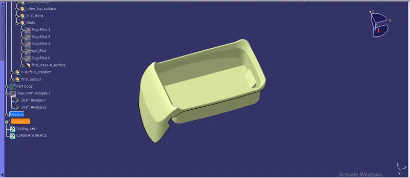
Note: As in the class-A surface, while measuring the fillet value we found in some areas there are fillet values as 1.5-2mm, so in this case if we reduce the thickness value, then it will be negative value and also we cannot give the sharp edges so we gave the standard fillet value as 0.5mm-1mm.
Also it is advicable to whenever we work on the fillet command, we need to work on shading with edges without smooth edges to view the model in a better way where to give the fillets.
Step 4: Creation of class-C surface
While creating the class-C surface, we always ensure that we make boundary of a class-A surface and where to close a class-A & class-B surfaces. Also we ensure that there is only a single boundary, if there are two boundaries then we have to create a separate C-surface for that also.
Knowledge: Creating class-C surface is closing class-A & B-surface, so there are two possibilities of closing the surfaces:
- When there is closing direction of class-A & class-B in the same direction of tooling axis, then we need to give minimum draft angle of 3 degree in outward direction to avoid the defects such as flash.
- When there is closing direction of class-A & class-B in the direction normal to the tooling axis, then we need to create the C-surface in the direction of normal to the surface to which the boundary is attached.
In this case we have closing direction normal to the tooling axis, so we need to create the C-surface normal to the surface on which the boundary of class-A surface is located.
- So we created two multi-extracts of class-A boundary and the surface which is attached to the boundary of class-A surface.
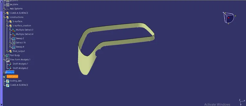
- Later we perform the sweep operation with referance surface opteration in the profile type as line and gave the guide curve as a boundary of class-A surface and referance surface as the surface which is attached to the boundary.
- And keep an angle of 90 degree in inside direction i.e, normal to the surface.
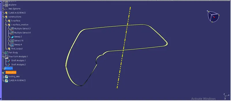
Note: As in this case we have two surface boundaries of class-A so we need to extract the inner hole boundary from class-A. And also the surrounding surfaces as well we have to extract it. But before that as we created C-surface boundary and class-B surface, we need to trim it and later join it with class-A surface and then we can trim this inner hole sweep with the final join.
Highlighter Point: We need to do the above note because the class-A surface has two boundaries and we need to sweep them separately. Also this hole cannot be cleared with our main tooling axis so we need to join the sweep and class-B and later we trim this with our inner hole sweep.
- So we trim the class-B surface with the sweep created for the outer boundary of the class-A.
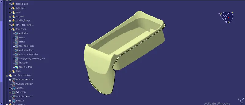
- Later we join the class-A with final Class-B & class-C trim.
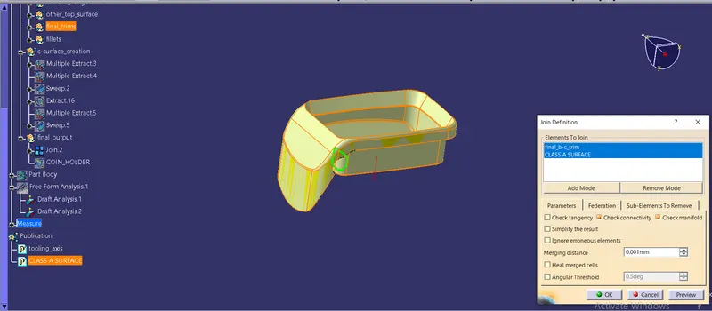
- Then we created multi-extract for the inner hole and and the surfaces surrounding it.
- And created a sweep for that in outward direction as with reference surface command.
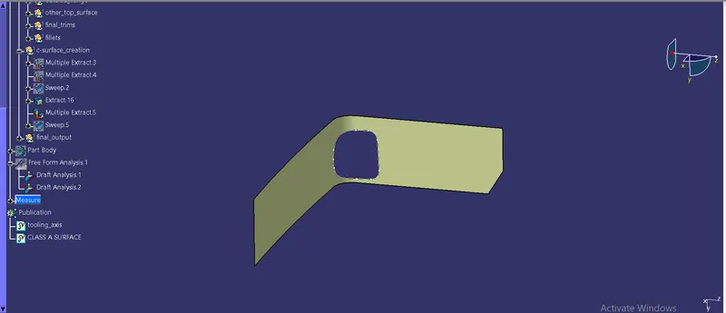
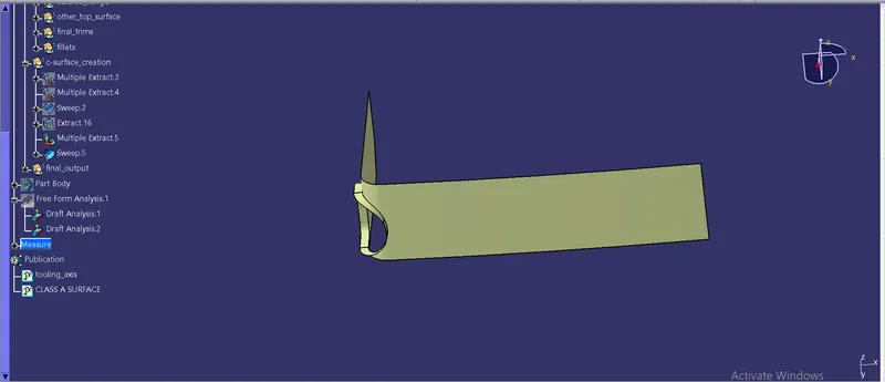
Step 5. : Final output of COIN HOLDER
- We trim the created join of class-A and class-B & C-surface trim with the sweep created for inner hole.
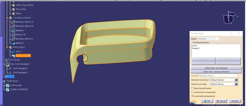
Conclusion: In this way we got the final output of class-A-B-C as a COIN HOLDER.
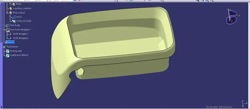
Step 6. : Creation of Closed Surface and Performing Draft Analysis on the Final Component
We create a closed surface of the final output obtained from part workbench using closed surface command.
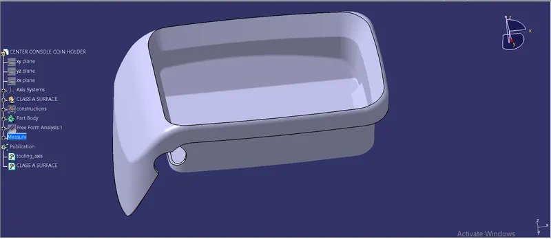
Draft analysis performance on the final closed surface component of a coin holder
As we have earlier discussed that the given class-A surface was not having any draft angle and the walls are at 90 degree so some areas are not clearing even after giving the draft angle as 3 degree.
- By clicking on draft analysis command and placing the compass aligning the tooling axis we get the final draft analysis as shown in the below image.
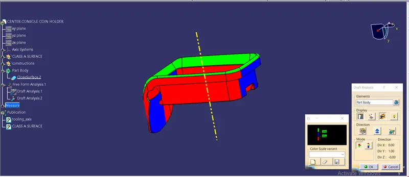
- But after seeing from the tooling acis direction, we found that all the vidible surfaces are clearing.
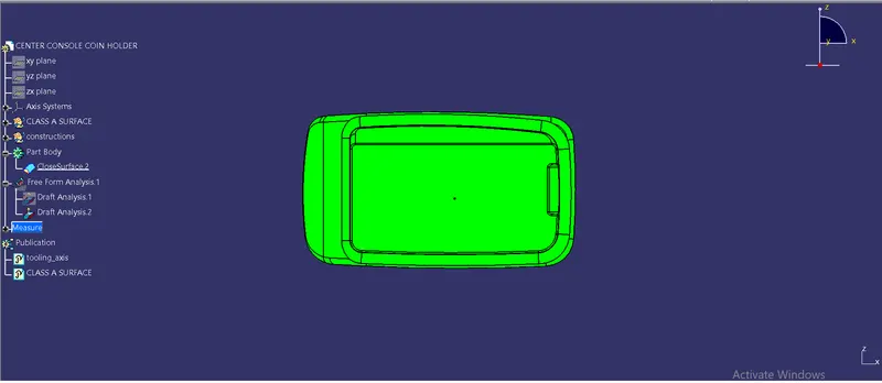
In this way way we perform the draft analysis on the final closed body of a coin holder.
Here are all the standard views of the final component of centre console coin holder.
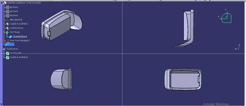
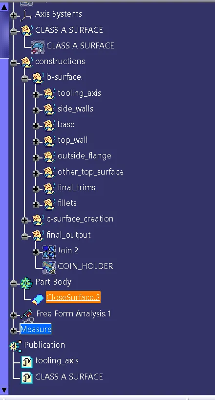
Also the final tree structure of the model is as follws: