Week 8 - Challenge 1 - Draft Analysis on a Fan Cover
DRAFT ANALYSIS ON FAN COVER
AIM:- TO CREATE THE TOOLING AXIS FOR DESIGNING THE MODEL OF FAN COVER AND PERFORMING THE DRAFT ANALYSIS FOR THE SAME.
WHY DRAFT AND DRAFT ANGLE IS NECESSARY IN ALL THE MOULDING PROCESSES?
- Draft is the angle in which the part is allowed to tapered to allow it to release from the mould. Adding draft helps the part to release the component from the mould smoothly. Most parts or applications require a minimum of 1/2 or 1 degree draft angle but however 3 degrees is widely accepted as the norm.
- In the process of injection moulding, the molten form when solidifies it needs to be ejected from the core and cavity and the closing & opening of core and cavity in only one direction.
- But the molten liquid when solidifies or cools it tends to shrink or clings to the core side of the mould due to which if the draft or ejection system is given in 90 degree or in the same direction of the opening of mould the solidified component gets clanged to the core and by the forceful ejecting may cause damage to the core & cavity as well as the component also.
- In order to avoid these frictions between core & cavity and the component draft is given at some angle so that after some displacement of lifting of cavity there will not be a damage to any the parts.
- By giving the draft angle to the core & cavity the component also gets drafted.
STEPS FOR CREATION OF TOOLING AXIS FOR DESIGNING THE MODEL OF FAN COVER
Step 1.
Check the connectivity of given class A surface for ensuring that there are no gaps between the surfaces. It is done either of the two following methods.
- Join the given class A surface, If error box pops up then there are gaps between surfaces.
- Take a Boundary option and see whether all the surfaces are continous without any gaps between them.
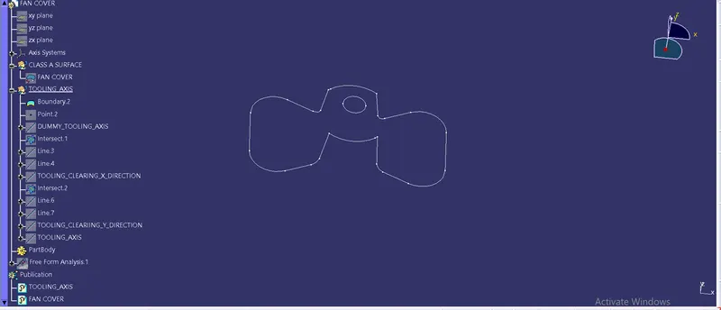
In the above image we have taken a boundary and and further highlighting the surface contuinity of the model.
Tooling Axis direction is the direction in which the core & cavity opens and closes. Next we will draw the dummy tooling axis for detrmining the exact position of main tooling axis as we dont know in which normal direction the draft angle must be given.
Step 2.
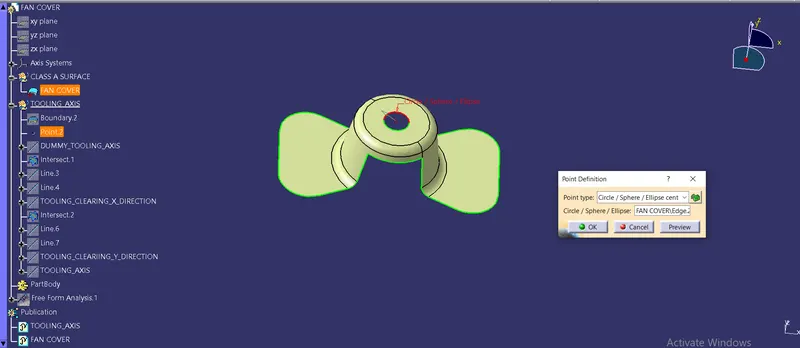
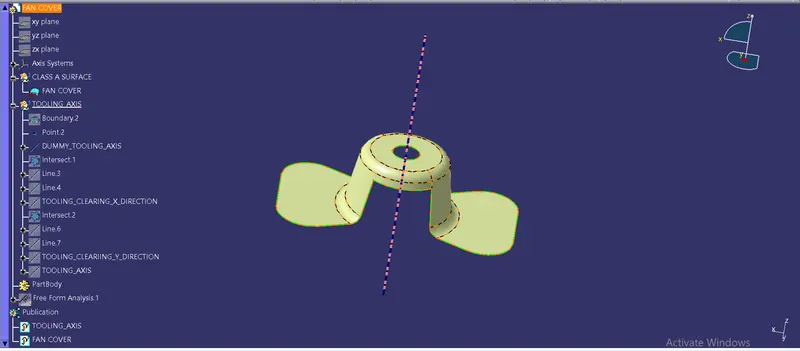
Check in which direction the tooling is cleared for all the surfaces and make an axis or line using point direction option by creating a reference point on the surface.
- Here we chosen Z axis as upper hole is cleared only in Z direction of main tooling.
- We create a line followed by creating a point on the top surface hole as a circle.
- And gave a highlighted pink colour and also shaded very well.
Step 3.
Our main purpose is to reduce the cost production and this can be done by minimizing the no. of side cores added to the mould.
In the given fan cover model there are two surfaces, So instead of creating a single plane on top surface which may lead to another tooling axis which may twist the model ultimately leads to another use of side core we use the axis system to avoid financial losses.
- We create an axis system over the point made on top surface as the origin.
- Then we create an intersection between Y axis system OR XZ plane and the Class A surface.
- And identifies the problematic intersection which may arise during the draft analysis.
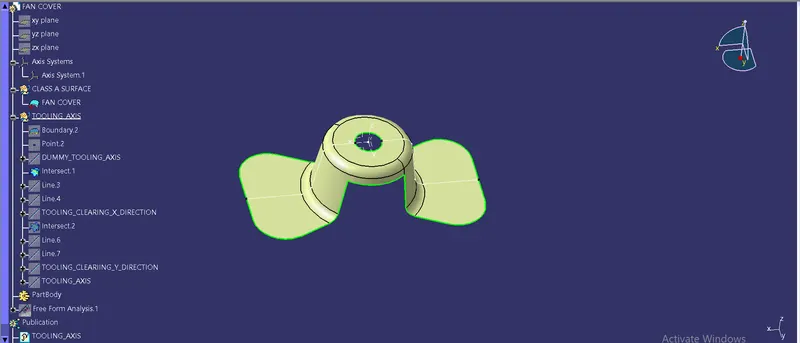
Step 4.
- Hiding all the unnecessary elements we make lines through the vertices and extend it very well.
- And make a bisecting line between parallel faces on which they were lying. In this case there were two parallel faces, so made a bisecting line of these two.
- The bisecting line formed was the tooling cleared for Y direction, So gave a name accordingly to avoid the confusions.
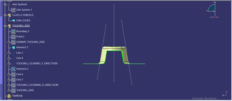
Step 5.
Same procedure was done for taking the intersection for X direction OR YZ plane and the class A surface and the output accordingly.
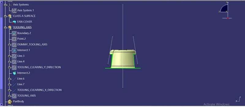
Step 6.
- Now bisect the axes of tooling cleared in both X & Y direction amd that was our main tooling axis.
- If we cant select the direction in which we want right click on lines + H (It will hide the lines).
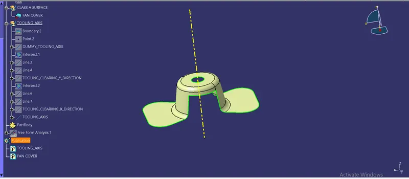
- Thus specified the line shaded yellow colour and ready for the Draft analysis.
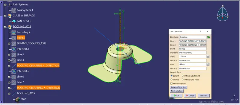
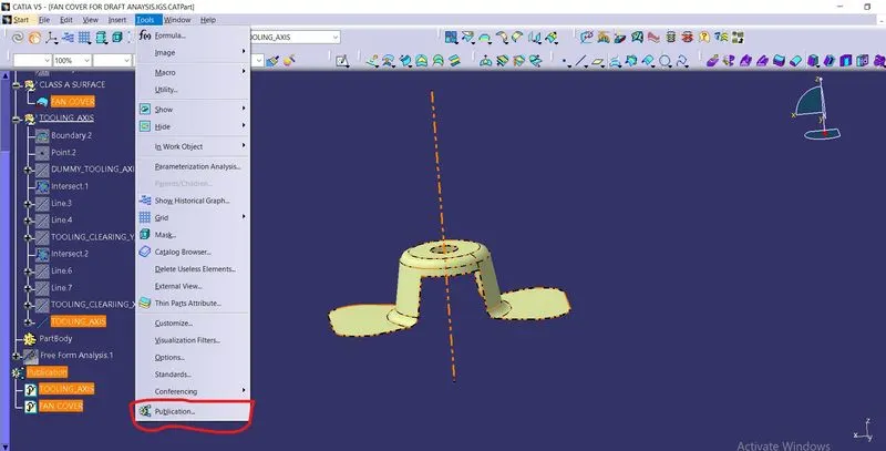
- After that publish the class A surface and main tooling axis together to avoid the so that they can be easily viewed and further no confusion arises.
- Click on both Class A surafce and Tooling Axis and then click on Tools and then Publications and then yes/ok to all.
STEPS FOR PERFORMING DRAFT ANALYSIS FOR DESIGNING THE MODEL OF FAN COVER
Step 1.
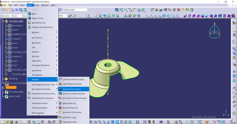
- Click on the Draft analysis option OR Go to Insert > Analysis > Feature Draft Analysis
- Place the compass situated at the top right corner of the window on the Tooling Axis and make sure that it is aligned with the tooling axis.
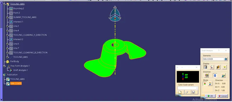
- OR else unhide all the planes and click fit to zoom in and then click on compass it will appear there and place it onto the the class A surface roughly and then zoom in and then fix it appropriately.
Step 2.
- Once it is done Selecting the element as class A surface, It shows green in colour.
- If it is not showing green colour adjust draft angle as 3 degree which is the standard angle 3 degree angle is mandatory.
- Once all the inputs are given properly and the output is satisfied by the design standards click on lock draft direction in draft analysis dialog box and click ok.
There are two modes of Draft Analysis:-
- Quick Analysis Mode:- It is done when we give 3 degree draft angle and quick draft analysis is done.
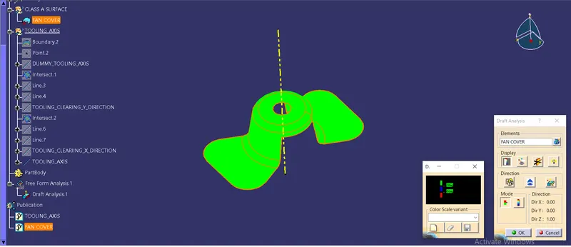
- Full Analysis Mode:- It gives us the full draft analysis of the model.It has 6 different ranges.
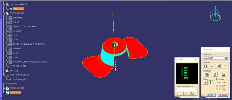
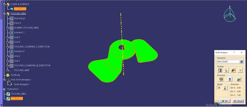
In the display option we four different options:-
- It hide or shows the colour which we discussed above. By using this option we can hide draft analysis 1 for ebtter vision and take a clear view of the model after updating the draft angle of 3 degree.
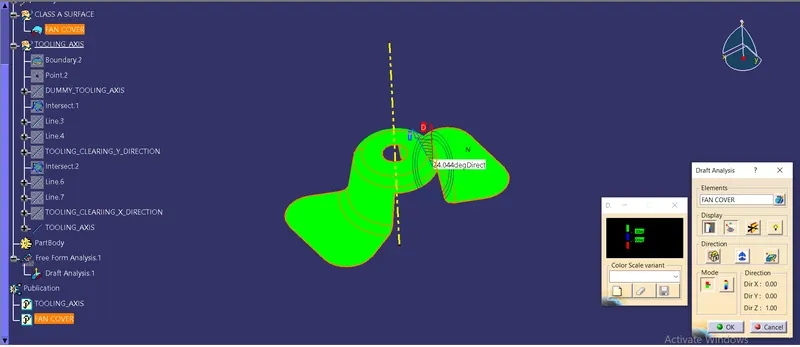
- It shows the analysis under running point. When we move the pointer on the surface it shows the angle made by the tooling axis on the surface. For each point on the surface gives a different angle made by the tooling axis.
- It shows the no highlight representation as this option is selected we can observe that the model is not selected but we can make the changes in the model. This opton allows us to see the defects on the edges also.
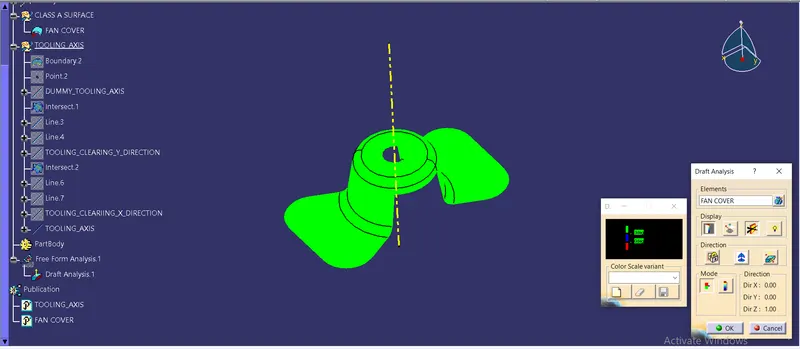
- It shows the light effect of the attained model and we can also highlight the light effect of the model.
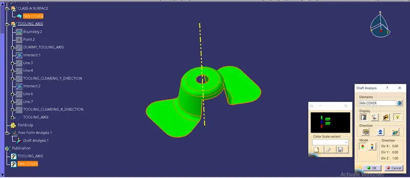
Finally we click on OK and the Draft Analysis is performed successfully.
Conclusion:-
Here we had created the main tooling axis and performed the draft analysis very well.
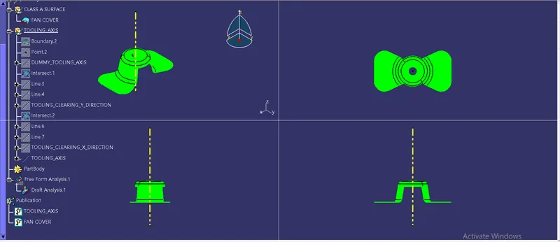
Here is the main tree How it looks like.-