Week 8 - Challenge 2 - Base Bracket Design
BASE BRACKET DESIGN
AIM: To create Class-B & Class-C surface from the given Class-A surface model of Base Bracket Design.
INTRODUCTION:
CLASS-A SURFACE: It is an aesthetic surface which is given as an input. Also it is an outermost surface.
CLASS-B SURFACE: It is a surface created from class-A surface for the thickness and all engineering aspects comes under the creation of class-B surface.
CLASS-C SURFACE: It is a surface that is obtained by joining the class-B & class-C surface.
STEPS INVOLVED FOR THE CREATION OF CLASS-B & CLASS-C SURFACE:
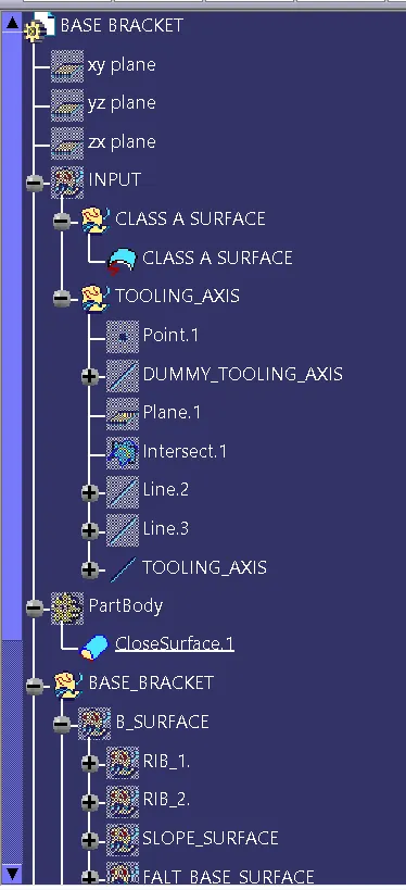
Initially we need to make a main tooling axis.
- Take a visual check in which direction the best possible tooling axis must be located.
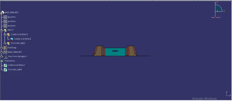
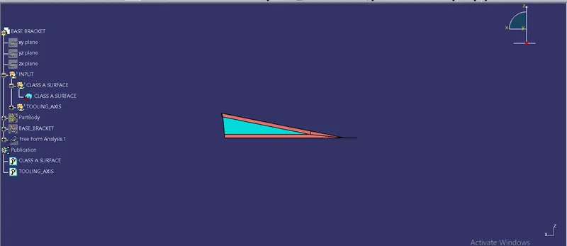
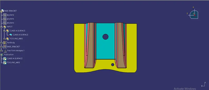
- In the above images the best possible direction would be Z direction because both the holes are clearly visible and can be cleared in the main tooling.
- Here we take the YZ plane as our intersection plane because in XY & XZ planes the holes in the class-A surface may not be cleared.
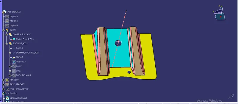
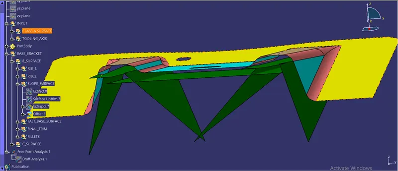
- Here we have four faces to clear with the tooling viz, flat surface, 2 ribs, slant surface.
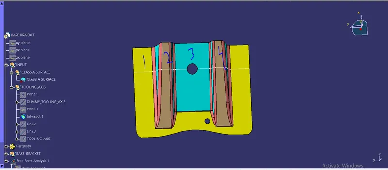
- By making the dummy tooling axis and creating the lines and extending very well and bisecting it and that will be our main tooling axis.
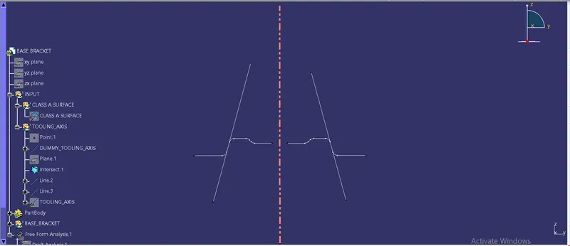
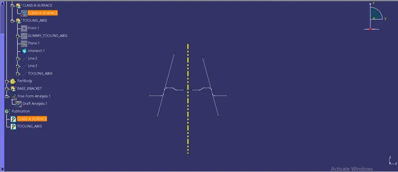
- Next accordingly make the draft analysis by taking the compass over the tooling axis and click on class-A surface.
Making sure we take the class-A surface & tooling axis outside by using publication option so that we may not confused or searching these two.
Now here are the steps for the creation of Class-B surface:
Steps for the creation of 1st Rib:
- Initially analyse the total parts to be cleared and we found that 2 ribs, slant surface and flat surface are the creations that we need to make.
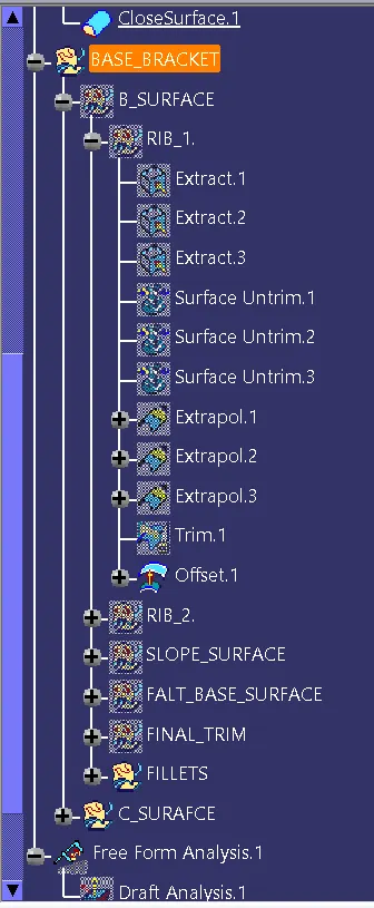
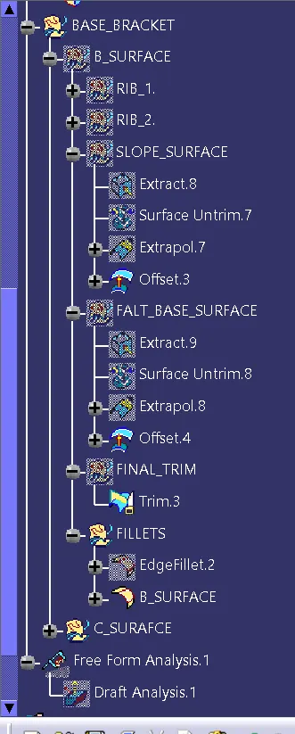
- Naming the geometrical sets very well and atking the 1st rib and extracting all the faces.
- Fillets are made at the last so there is no need to take that as a separate part.
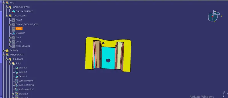
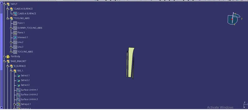
- Then untrim all the extracted surface one by one or in a single go. and extrapolate all of them very well one by one about 10mm each.
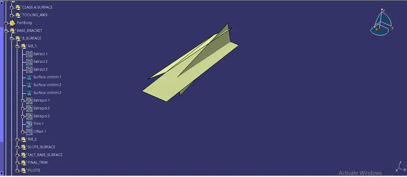
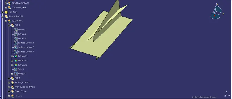
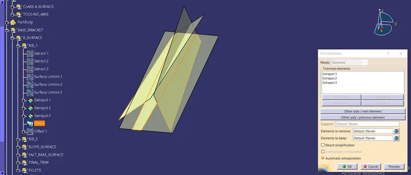
- Then trim all of the surfaces by checking the shape the rib by unhiding the class-A surface. We do it in a single go resulting in the reduction of steps.
- Now offseting the trimmed surface by 2.5mm thickness downward direction because Class-B surface is made in the downward direction usually. Give the colour accordingly as it is a surface of Class-B surface
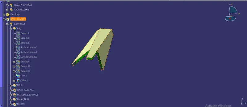
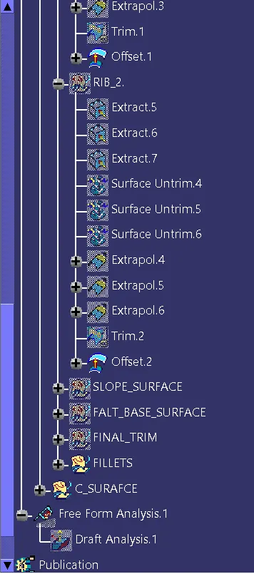
Steps for the creation of 2nd Rib, Slant surface, Flat surface are same.
The procedure is same as that of made for 1st Rib.
Steps for the creation of 2nd Rib:
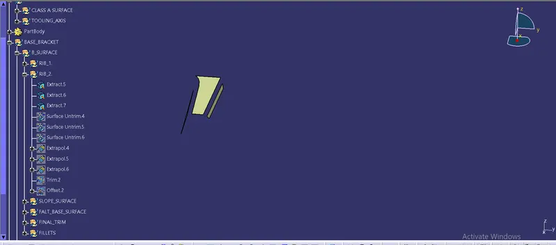
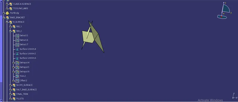
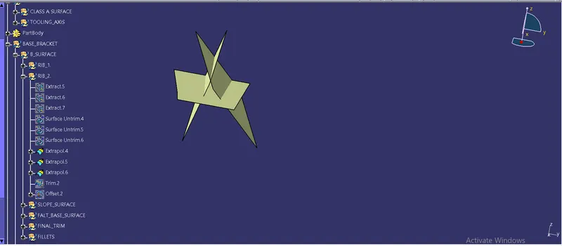
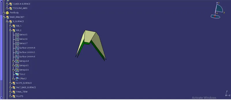
Also making sure that to check with the Class-A surface.
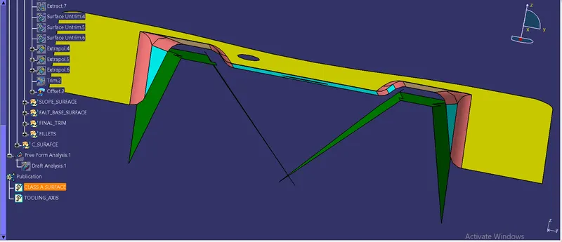
Steps for the creation of slant surface:
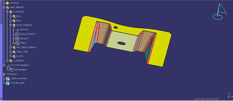
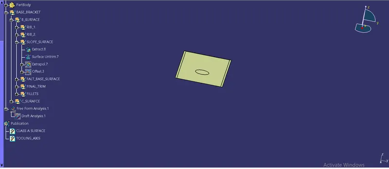
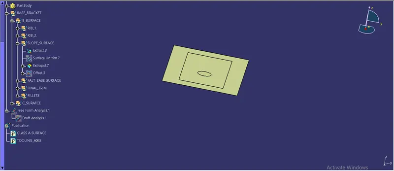
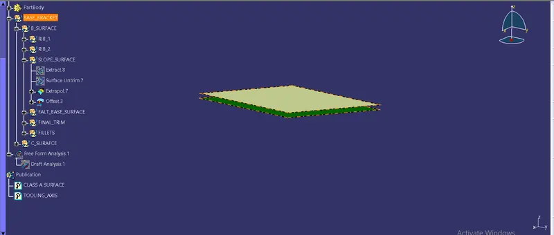
Make sure that it is well intersected with ribs so that at the time of trimming it may not give us a problem. And checking with the class-A surface.
Steps for the creation of Flat Base Surface:
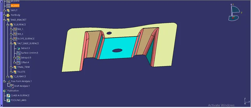
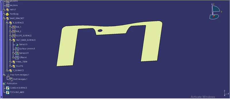
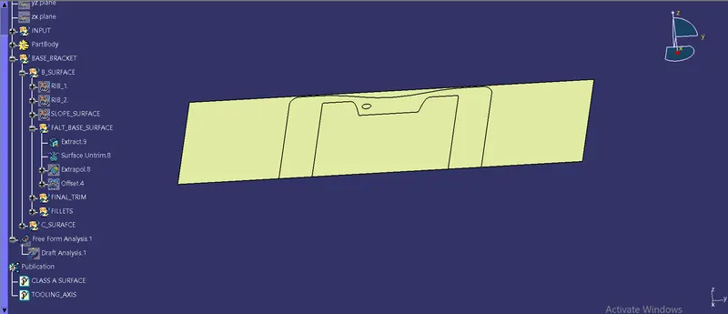
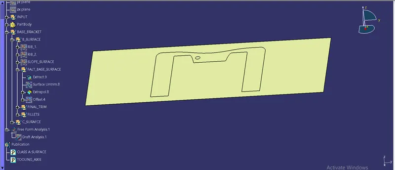
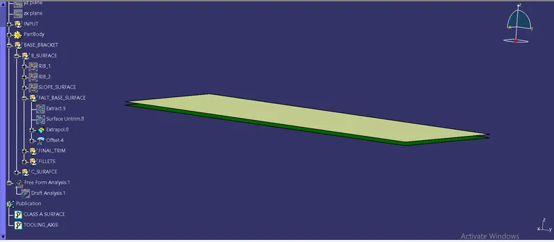
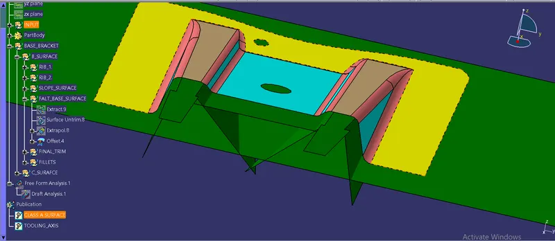
Now the final trim is done for the model by taking the desired output of 2 ribs, slant surface, flat base surface.
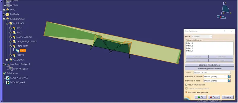
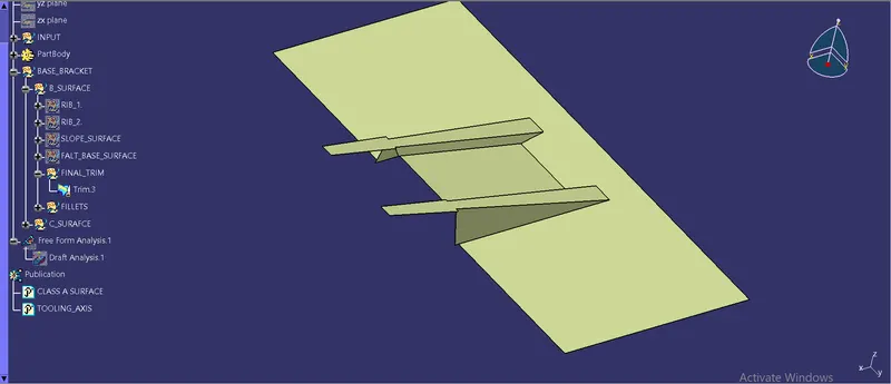
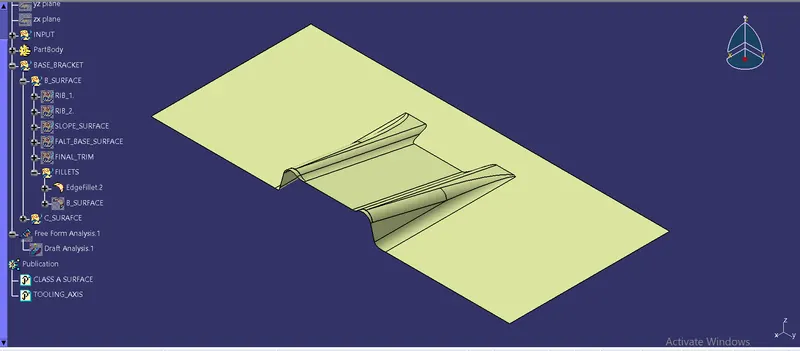
Steps for the creation of Fillets on the final trimmed surface:
- Calculate the values of fillets on class-A surface by using measuring item and measure between using vernier caliper.
- Always select the surface only for measuring the thickness and use vernier caliper for measuring the radius values in any geometry mode but more probably picking point is advisable.
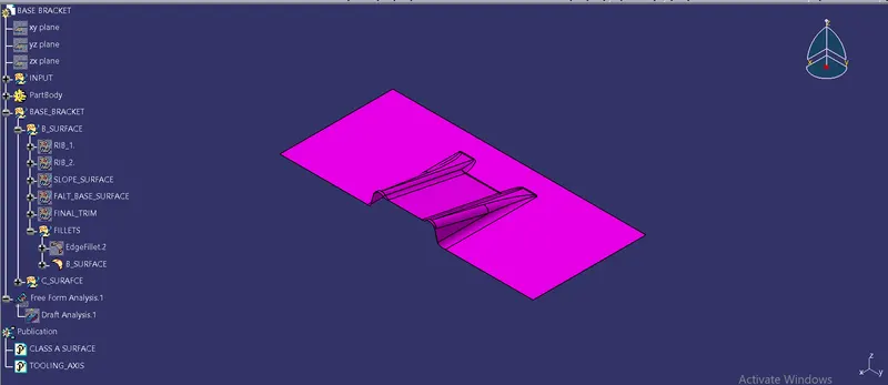
- Finally our Class-B surface is created.
- Name it accordingly and give the colour very well.
Now here are the steps for the creation of Class-C surface:
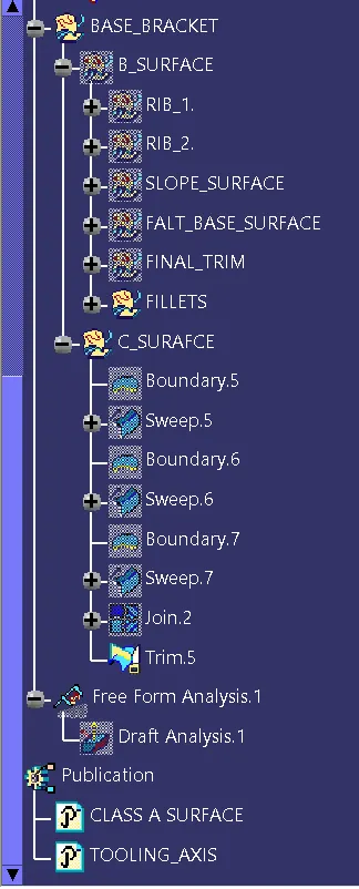
- Initially make a boundary for the Class-A surface.
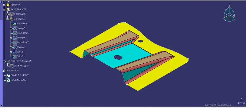
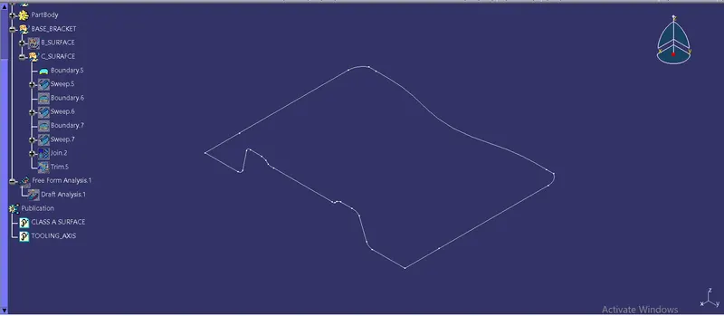
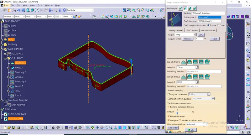
- Secondly, unhide the tooling axis and slect the sweep option and click line option with selecting WITH DRAFT DIRECTION as Subtype and guide curve as the boudary created for the class-A surface and direction as th tooling axis.
- Make the draft angle as 3 degree which is globally accepted or by the rules and give particular length and select the downward direction arrow so that it will along the tooling axis in downward direction.
- Make sure that the fill twisted area and compute C0 vertices as twisted areas boxes are checked.
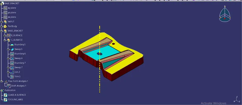
- Similarly do the same procedure for both the circles and sweep them accordingly.
- This can be done in the above step by extracting the outer boundary and circles and then sweeping them separatly.
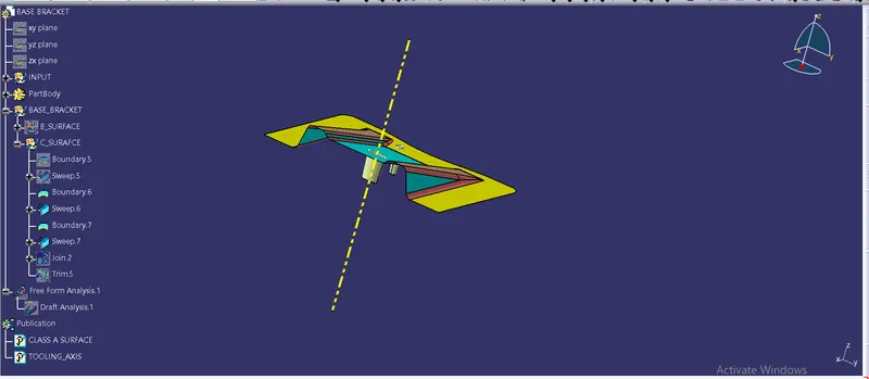
- Now we join all the sweeps made and the class-A surface togetherto form a desired single output.
- Finally we trim this join of class-A surface and the class- B surface to form the final output as class-C surface.
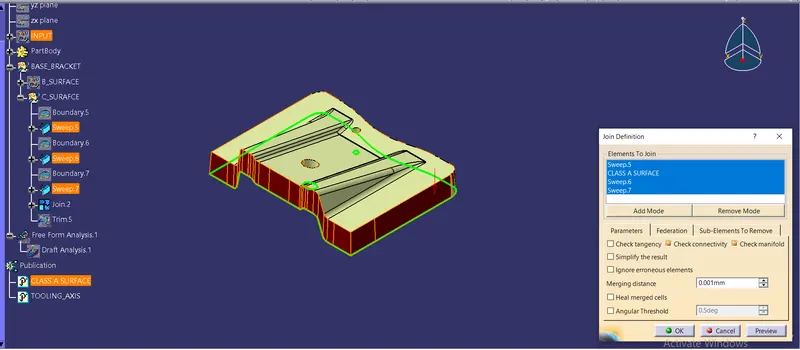
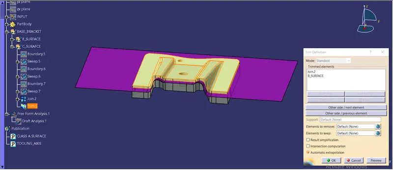
As a result we get a class-C surface as our output.
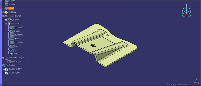
At last dont forget to check any gaps in Class-C surface.
- This can be done by checking the boudary option and it throws a message i.e, there is no gap in the final surface.
- Also when we check surface boudaries option in Tools > options > display > visualization > surface boundaries.
- And by join option and by clicking on the final surface if there is no green colour boundary then the Class-C surface is ready manufacture.
Now converting this class-C surface into a solid body we go to part design workbench and Defining the partbody in the split box we find closed surface click on the surface and ok, it will get converted into a solid body.
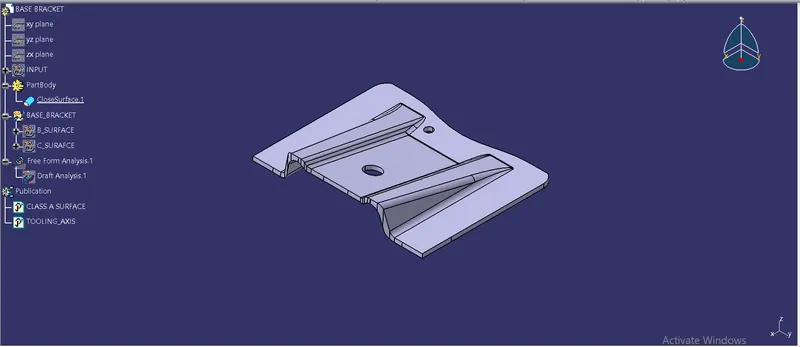
CONLUSION: In this way the class-B and class-C surfaces are created from the class-A surface.
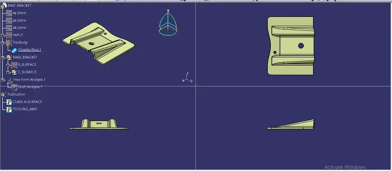
Here are the tree structure and all the views of the final Class-C surface design.