Week 8 - Challenge 3 - Switch Bezel Design
SWITCH BEZEL DESIGN
AIM: To create the switch bezel plastic component from the given class A surface model and also to perform the draft analysis of the final model of swith bezel.
SWITCH BEZEL: A Switch bezel is a switch which is power operated for the opening and closing of the window glass in automobiles and there are various swith bezels which is power operated for different functions.
Here we are going to design the swith bezel for the window glass.
Steps for the creation of swith bezel design as a solid part:
Here we are provided with the class-A surface and from that we have to create class-B & class-C surface.
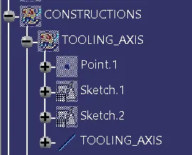
Step 1: Creation of Tooling axis.
- Initially we join the given class-A surface to check whether there is any gap in the surfaces. And we give a colour to component very well.
- Now we took visual check and manual check the best tooling axis position.
- We found that there are five different surfavces avoiding the fillets as they are difficult for the creation in class-B surfaces. So all the flat surfaces can be cleared easily except the pocket area. So for that we create a point on on the base surafce to clear all the side walls of the pocket area.
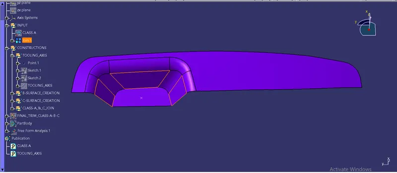
- Then for the tooling axis we need to draw the tooling direction clearing in X & Y direction respectively. This we done in the positioned sketches.
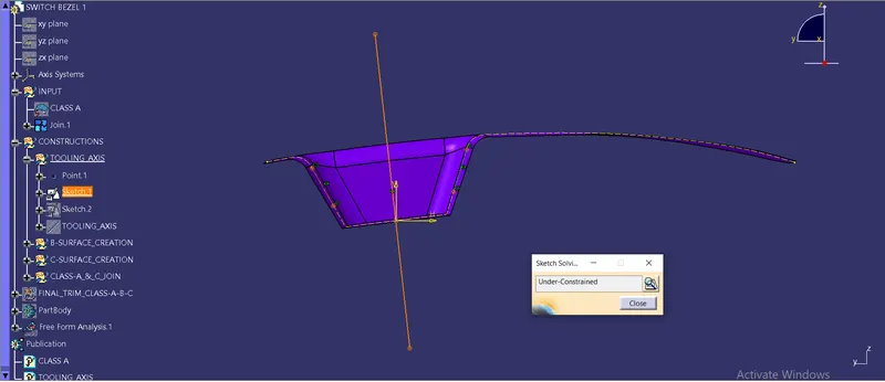
This sketch 1 is for tooling direction cleared for X direction. Here we need not to worry about the iso-constraints of the sketches, because our main focus is to create the tooling axis.
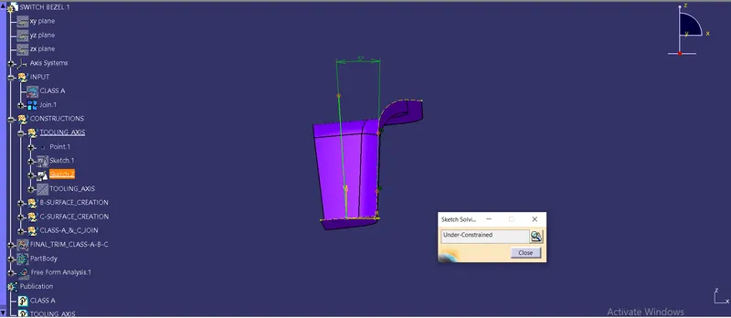
Sketch 2 is for the tooling direction cleared for Y direction. Here we dont have another surface to draw the so we took a referance line from the origin and extended very well and keep the angle between them as 5 degree. These values are taken on random basis. As we know the standard draft angle must be 3 degree but here we took as there may not be further deviation and take 5 degree as the angle.
- Now we got the tooling direction clearing X & Y direction and we need to create a bisecting line and that will be our main tooling axis. And give a colour and shading accordingly and took the class-A surface & tooling axis outside as publication.
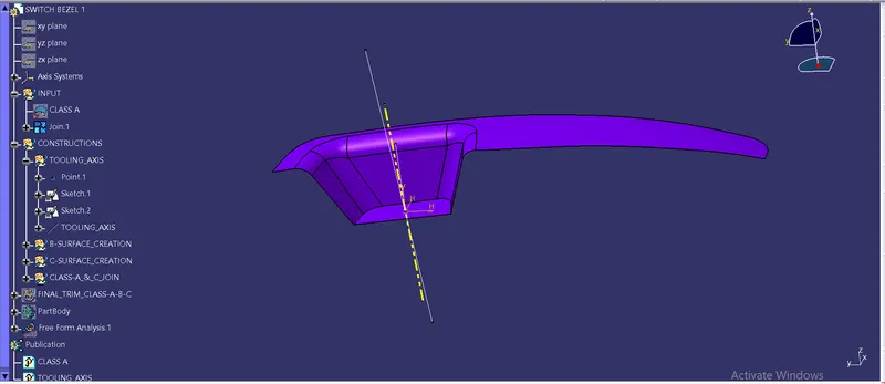
- Then we took a draft analysis of class-A surface using our main tooling axisby keeping draft angle at 3 degree.
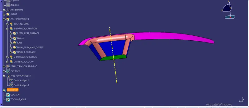
- Click ok ok to continue.
Step 2: Creation of class-B surface.
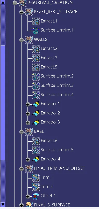
- Initially we made a geometrical sets for ecah surfaces we joined at the first.
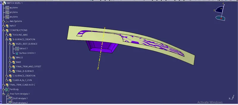
- In the bezel rest surface, we extract it and untrim it.
- But we are not going to extrspolate it because it is the last surface to be worked on and afterall it is already extrapolated by looking to it.
- Now same for the 3 side walls. We extracted them and untrimmed very well. Here also we extrapolated the untrimmed surface and extended it across the bezel rest surface.
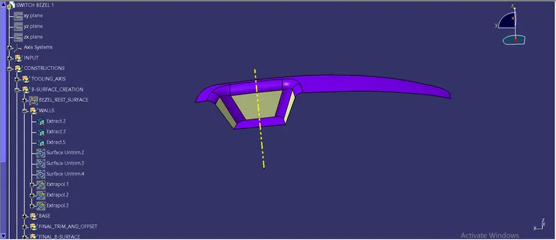
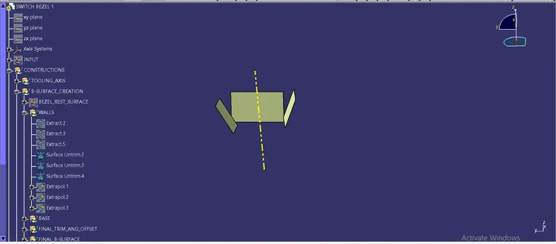
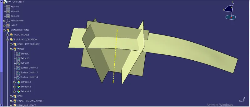
- Also we extraced the base surface and extrapolated it very well.
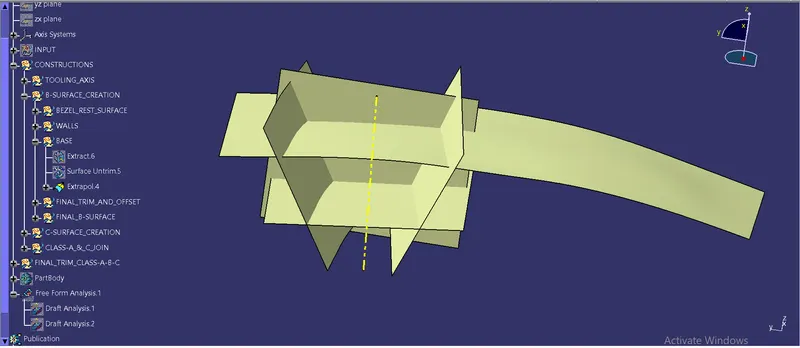
- And then we trimmed the side walls first and then we did the final trim over the untrimmed surface of bezel rest surface and the extrapolated surface of base with the trim of side walls.
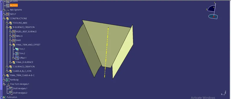
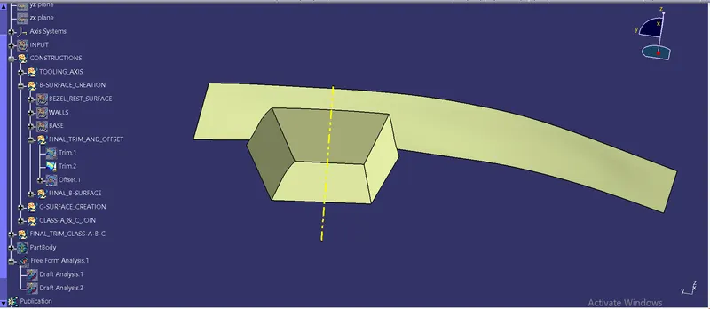
- Also we offset the final trim with 2.5mm downward direction because the class-B suraface is usually made below the class A surface for the final trim ofter class-A & class-C surface are joined together.
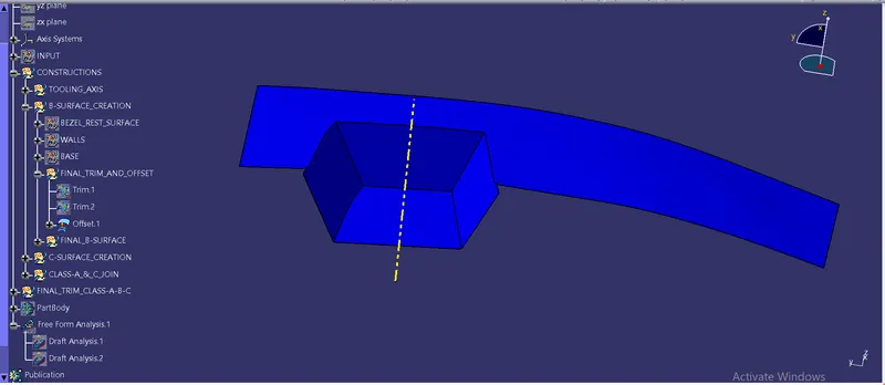
- Now we did the fillet operation to obtain the final class-B surface and give a colour to get highlighted class-B surface.
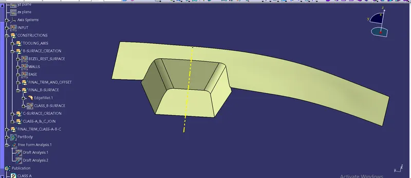
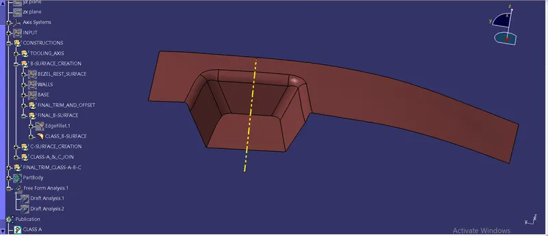
Step 3: Creation of Class-C surface
Now we are supposed to make a class-C surface. Initially we name proper geometrical sets for the creation of final class-C surface.
- For the class-C surface creation we need a bounadary or a guide curve and a tooling axis.
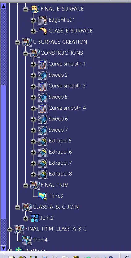
- So we created a smooth curve over the boundary of join of class-A surface and also did a visual check in how many parts we have to create a smooth curve. Since we usually use sweep command to create the class-C surface we perform the sweep operation for each smooth curve.
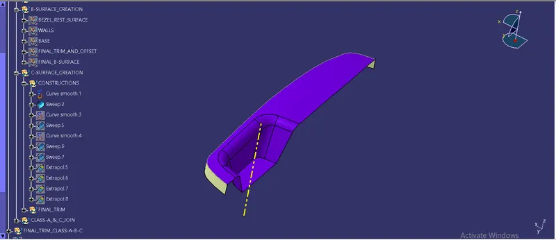
Note: Here we may create the boundary all over the join surface of class-A but creating a simple boundary and performing sweep operation created lot of patches so we creeated a smooth curve and then we sweep it accordingly.
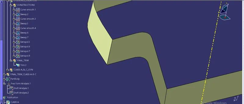
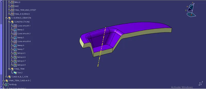
- Now we create the smooth curves and sweep it accordingly and as shown below.
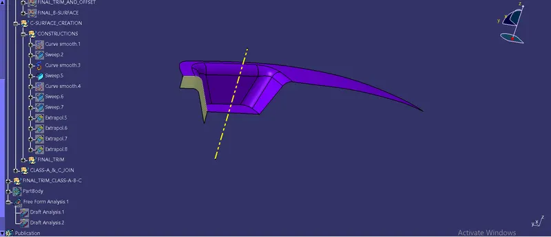
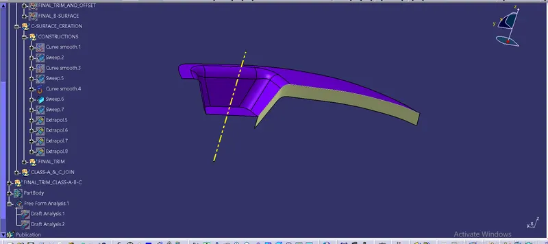
- For the base we did not crreate any smooth curve nor any boundary because the base is a flat edge and we can directly sweep it with the tooling axis.
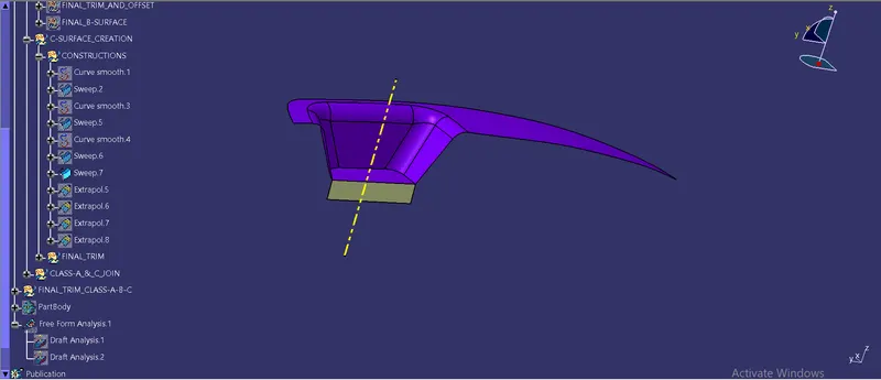
- Now here we need to extrapolate all the sweeps we created, because we had swept in outerward direction with 3 degree draft angle, so they had not perfectly joined together and there is a gap between them.
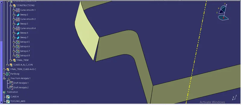
- Hence we extrapolate all the surfaces with 10mm and laterwe trimmed it together.
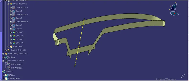
- Now we did the final trim and made a separate geometrical set for this.
Step 4: Join Class-A & Class-C
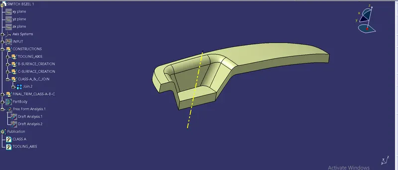
Now we got the final class -C surface and we need to join the class-A & class-C surface together in a different gemetrical set.
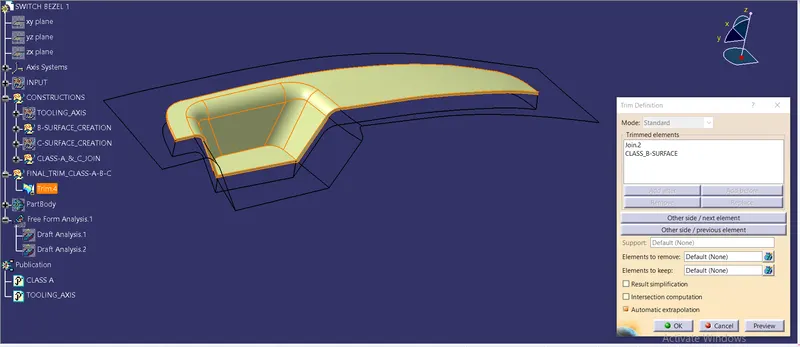
Step 5: Final trim of class-A-B-C
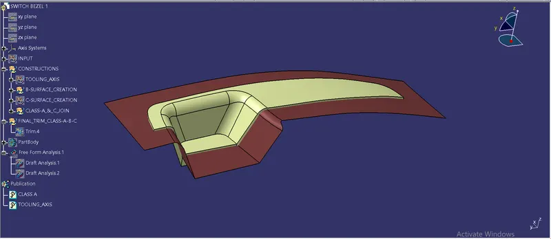
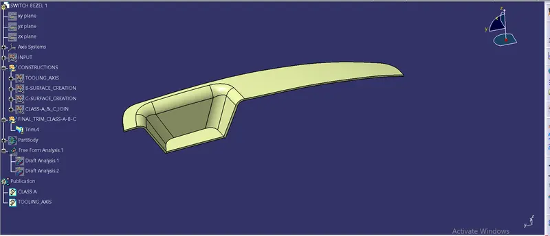
Here we going to trim the final join of class A & class-C with class-B as shown below.
Step 6: Conversion of solid closed surface from the final output in surface workbench
Now we got the final output of joined class-A-B-C surfaces and we need to convert it into the solid body by switching into the part design workbench and choosing the closed surface command.
Note: But before that we are supposed to check weather there is any gap between the surfaces, if there are any we need to resolve it by giving the merging distance in join command of Class-A & Class -C surface by 0.003 which is the industry standard and checking it. Also if this is not enough we can go through extrapolating the surfaces and trimming them again. And then proceed to the part workbench and making the closed surface of final output.
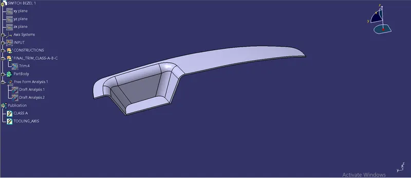
Step 7: Final Draft Analysis on a final output obatined in part workbench
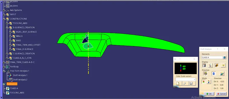
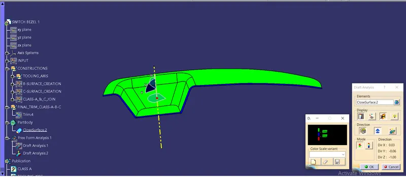
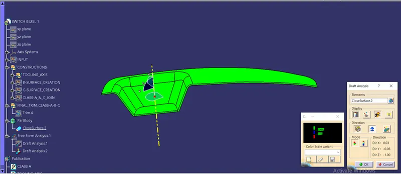
- Here we do the draft analysis for the final output by clicking on draft analysiis with the tooling axis and keeping the compass exactly on the tooling axis facing the Y axis .
- While giving the draft angle we found that on 3 degree it shows blue in colour which means while manufacturing or moulding it may create the friction also it mean the angle is between 0-3.
- So we change the draft angle to 2.9mm because at 3.1mm it shows in blue colour only.
- These are happened on the vertical faces of the component that means on the class-C surface, So we resolve it and finally done the draft analysis succesfully.
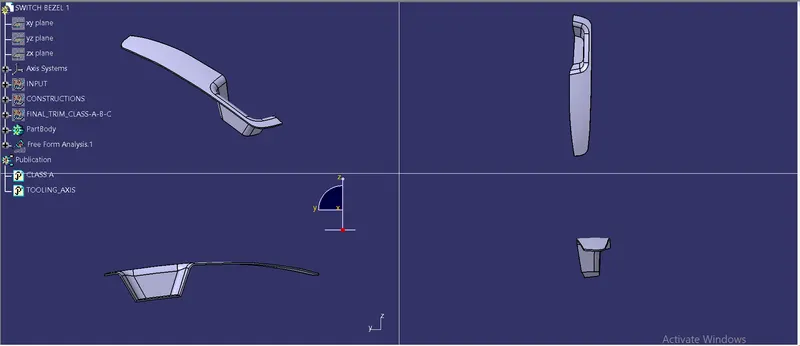
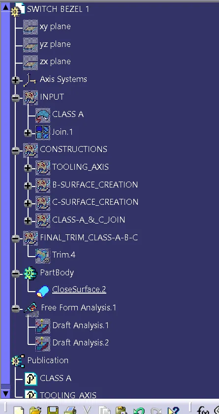
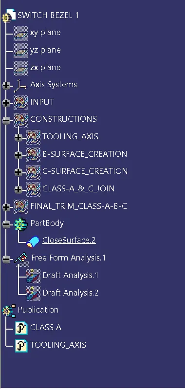
Here are all the standard views (Isometric, front, top & side) and the tree structure.