Week 8 - Challenge 4 - Coin Holder Design
Objective: To create class B & C surface for the given component which is coin holder using Catia V5R21 with engineering standards and to perform draft analysis for both class A surface and the final component by defining the tooling axis.
Procedure:
1. Perform connectivity check for the given component i.e.,. coin holder which ensures any flaws in the component.
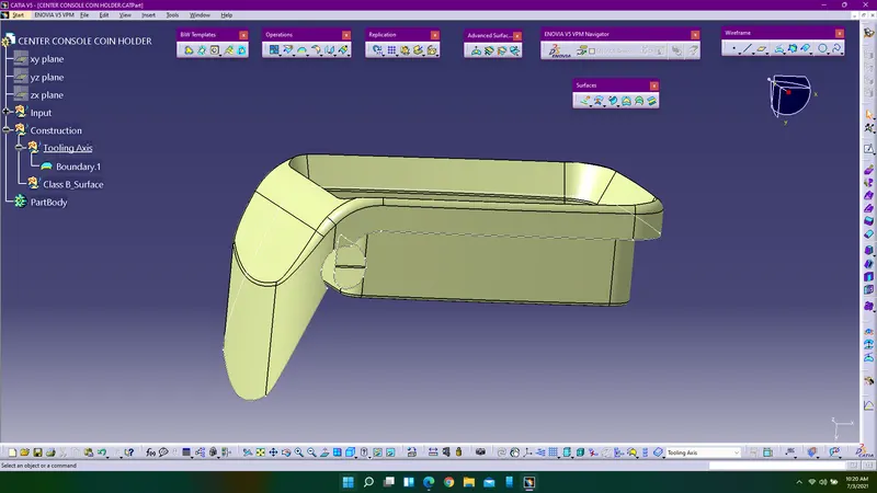
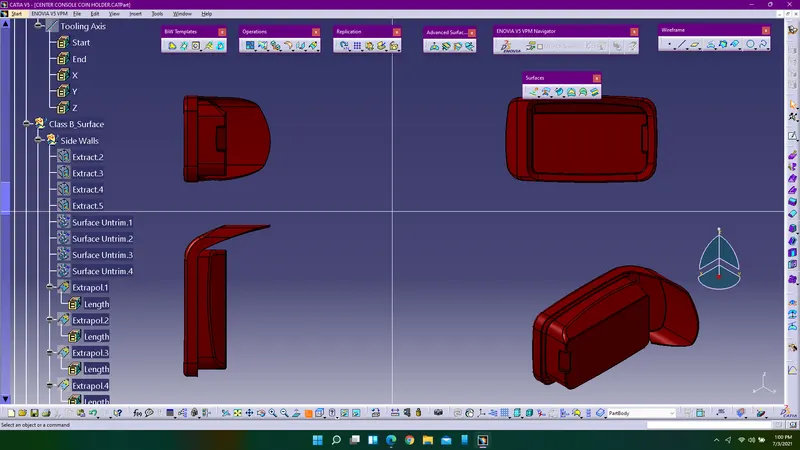
2. Define the proper tooling axis for the given component by selecting the appropriate direction to open core & cavity and extract the surface required for the tooling axis and create a point over it.
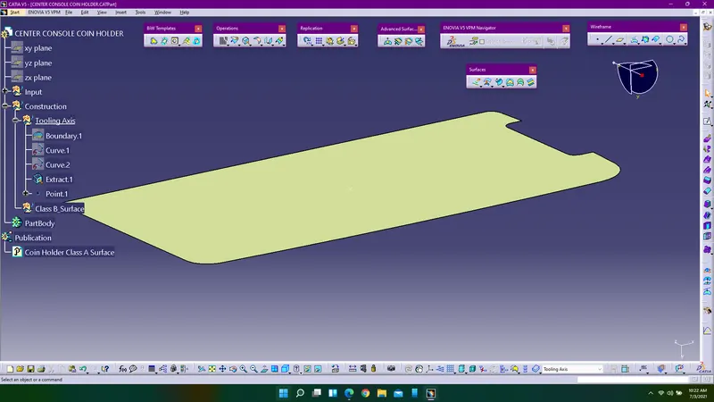
3. Since the given component surfaces do not have any draft angle, so we can draw a line perpendicular to the surface which is extracted and perform draft analysis on the class A surface.
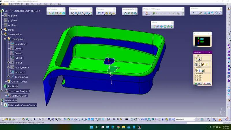
4. Now extract the walls of the class A surface, untrim them and extrapolate them using multiple extract, untrim and extrapolate command.
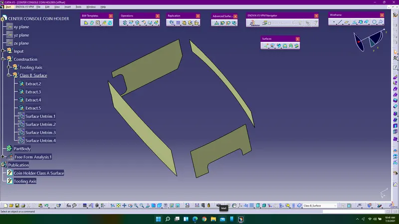
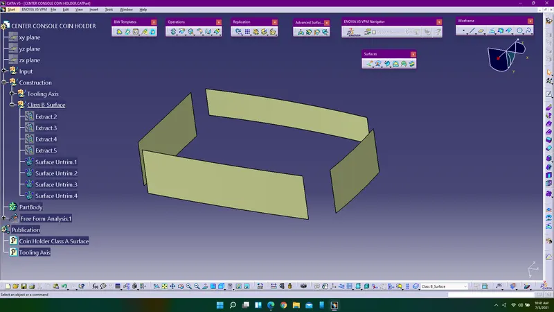
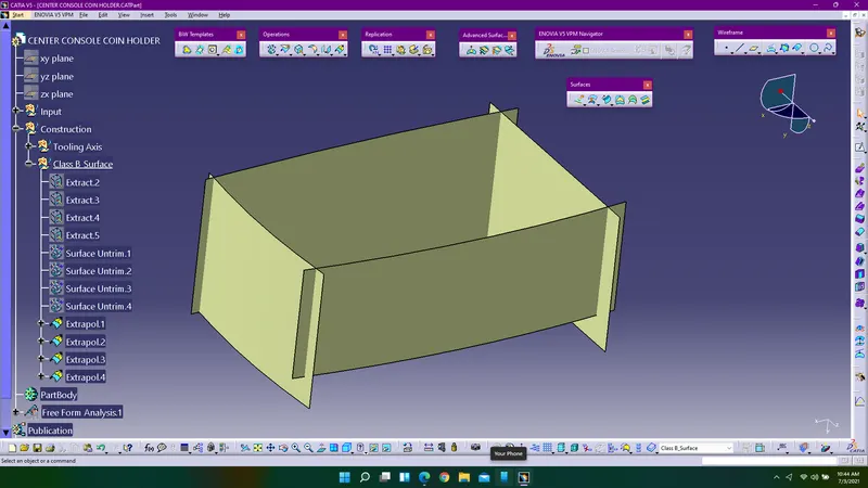
5. Offset them to 2.5mm and trim the extraportions using trim command.
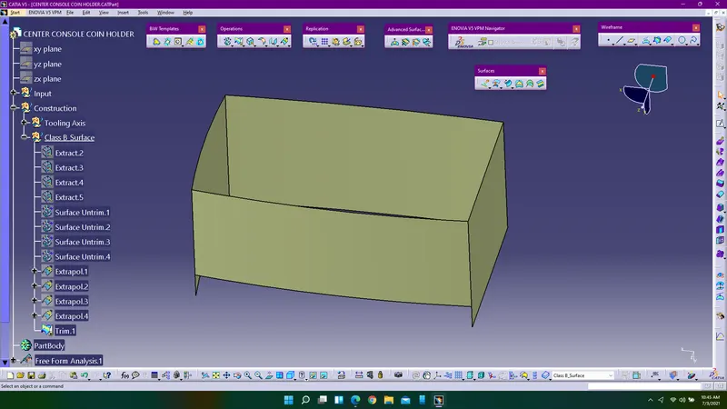
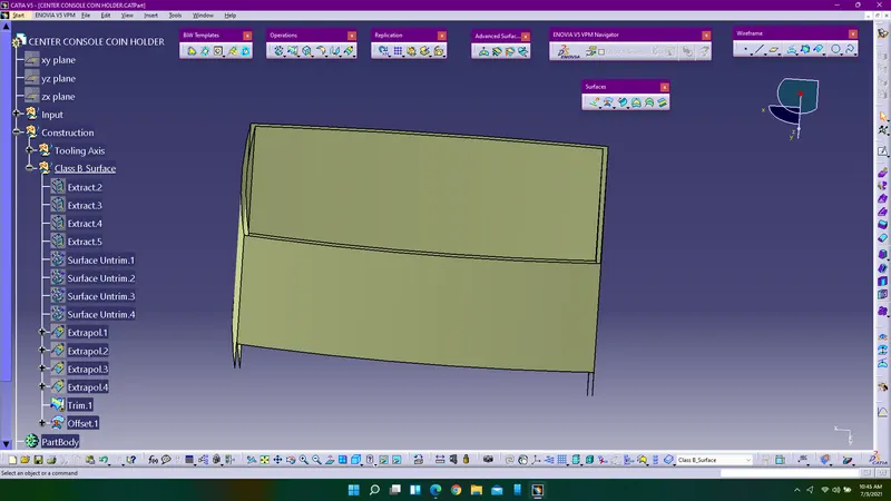
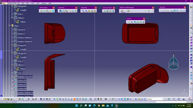
6. Work on the base of the coin holder in the similar manner i.e.,. extracting the surfaces and untrimming them and extrapolating them.
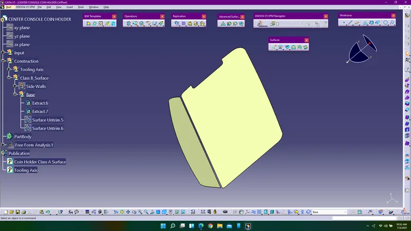
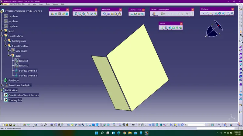
7. Offset them to 2.5mm and trim the excess portions.
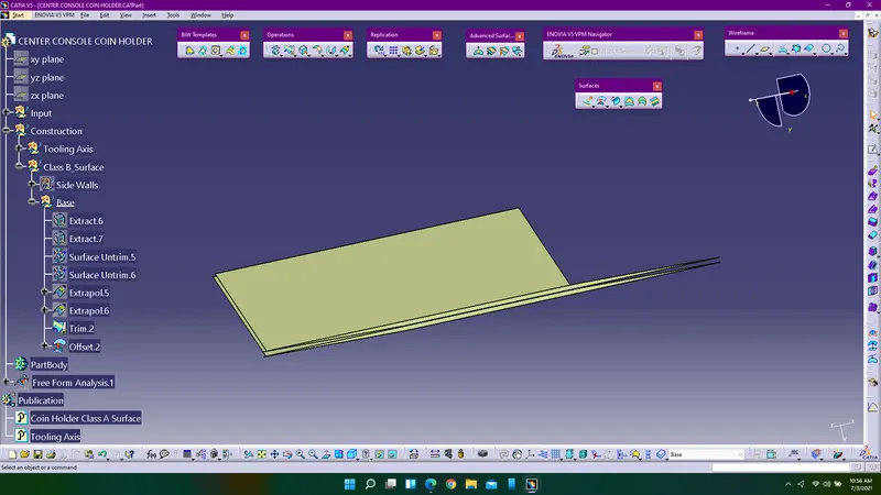
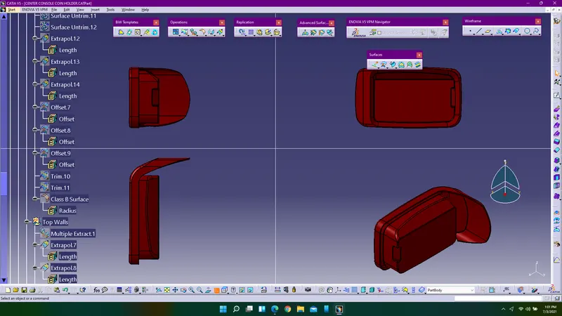
8. Now trim both the walls and base to create this shape.
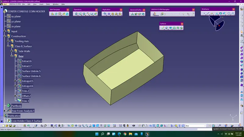
9. Next step is to work on the top walls of the coin holder, extarct the surfaces using multiple extract, extrapolate them and offset them to 2.5mm and trim the top walls with the trim obtained from the above step and provide the appropriate fillets to it.
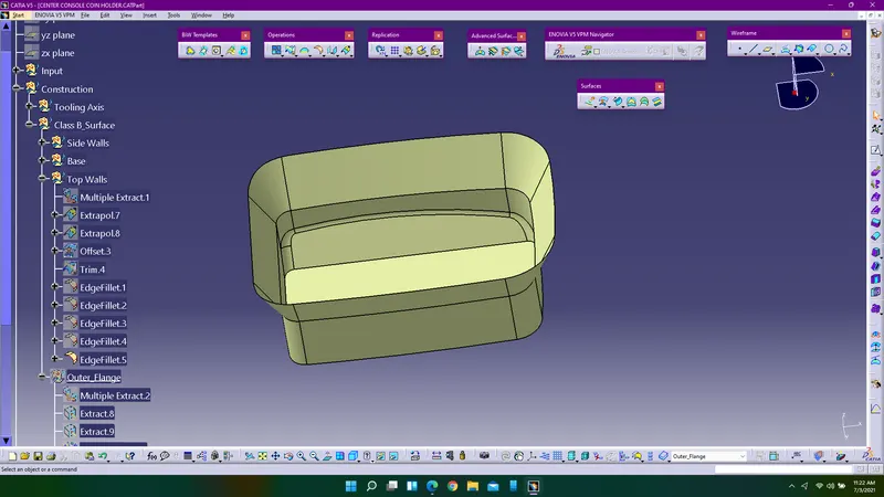
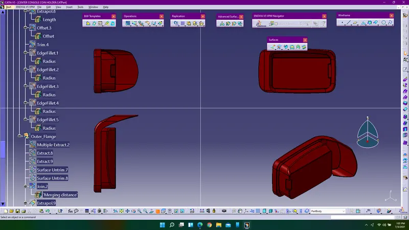
10. To work with the outer flange extract the surfaces and extrapolate them using curvature and point continuity and offset them 2.5mm. Make sure your are offsetting in the proper direction which is the below the A surface.
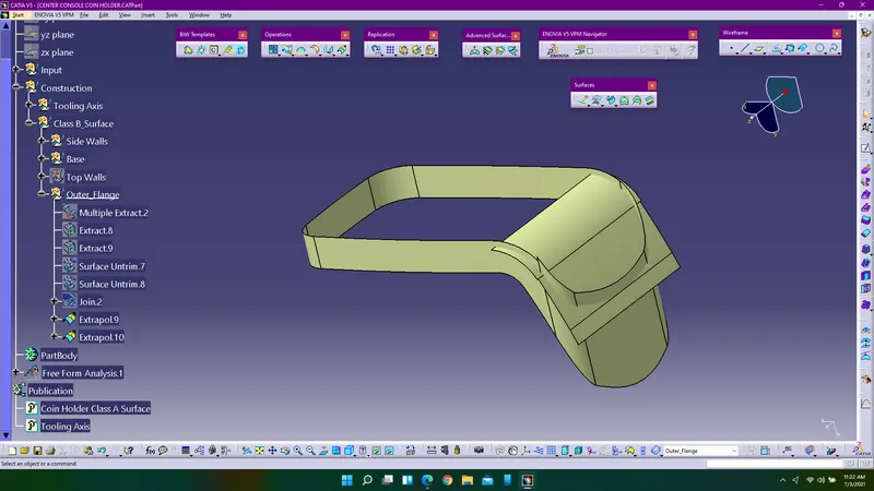
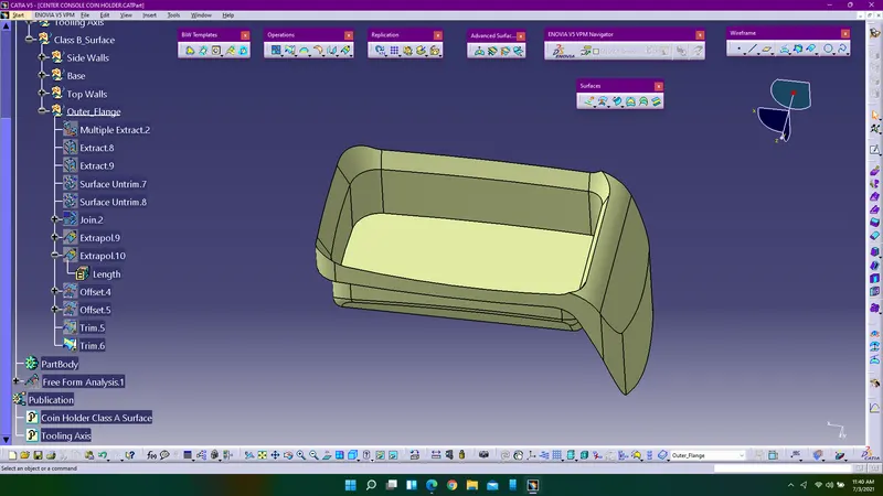
11. Trim all the surfaces and get the required shape according to the class A surface by removing excess portions of the surfaces.
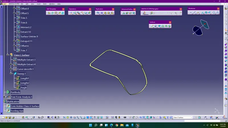
12. Create class C surface with the help of extracting the boundary of the class A surface and smooth the boundary curve and using sweep command extrude the surface with the reference surface option in the sweep command and apply an 90deg angle to it. Give the extrude distance as 4-5mm.
13. Trim both the class C & B surface and apply all the fillets on the B surface using edge fillets.
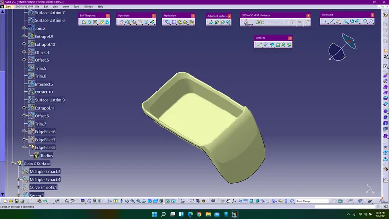
14. Next step is to create the pockets on the B surface, to create them extract the required surfaces and obtain the boundary of the pocket to be created and to create the C surface using sweep command and also extract the surfaces for the second pocket, untrim them and exprolate them make sure your are providing 2.5mm offset distance them and trim them with the B surface and obtain the final model.
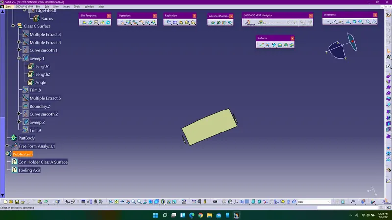
15. Join all the surfaces i.e.,. Class A & B surfaces using join command since we have used trim to remove the excess portion of the surfaces of class C so there need to be join them.
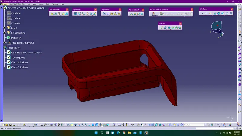
16. Enter into the part design and using close surface convert the surface model into solid model and publish all the three surfaces along with the tooling axis perform draft analysis on the final component.
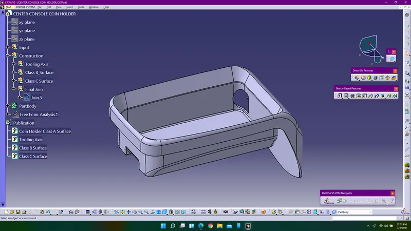
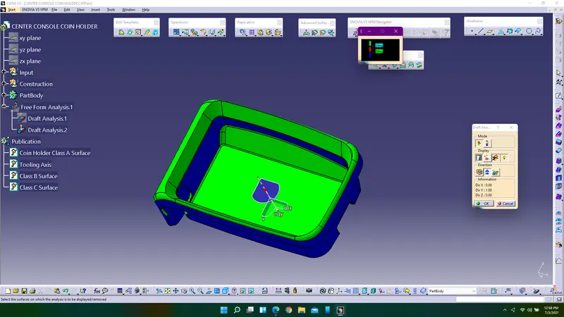
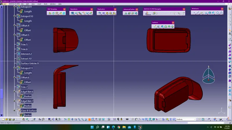
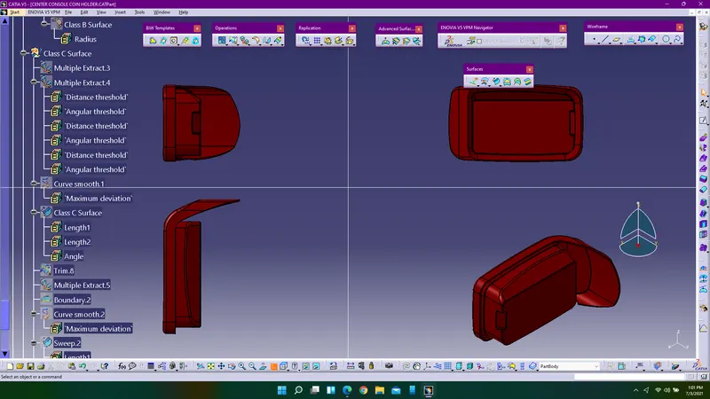
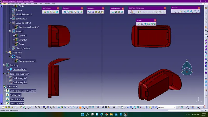
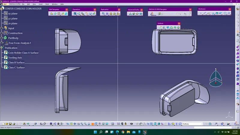
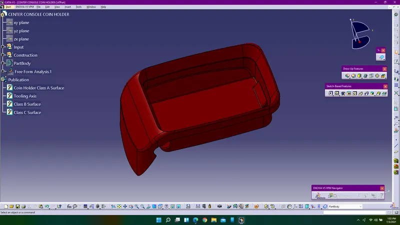
Feature Tree Diagram Of Coin Holder:
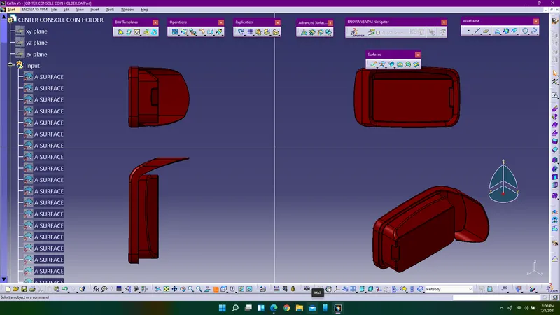
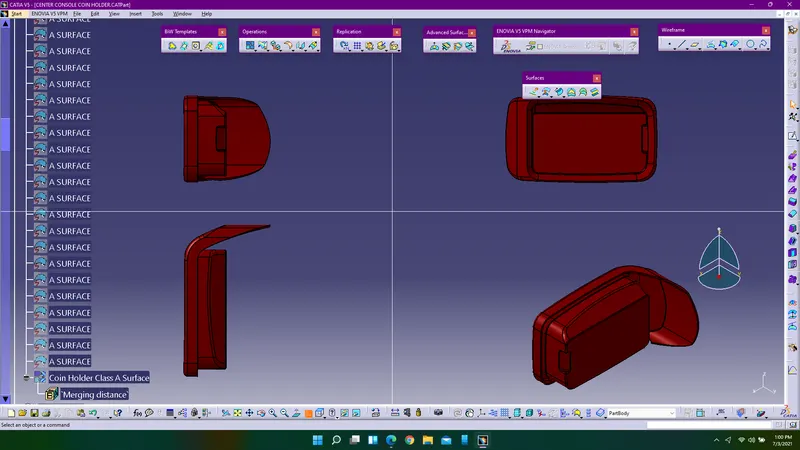
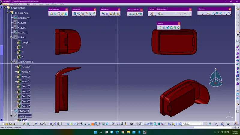
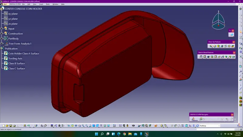
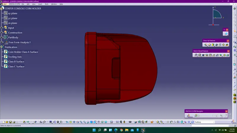
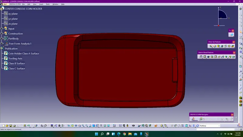
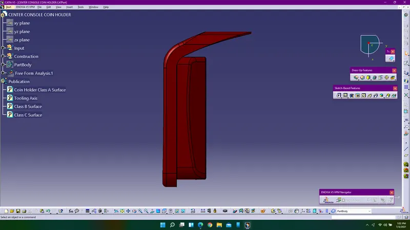
Views Of Coin Holder:
Conclusion:
Class B & C surfaces were created with engineering standards and performed draft analysis for both class A surface and whole component and publsihed the required surfaces and converted the whole surface component into solids.