Week 8 - Challenge 4 - Coin Holder Design
AIM:
To create the part model of the surface classs A provided by creation of the B and C surfaces.
OBJECTIVE:
The coin holder model with the design features involved and creation of the surface thickness necessary. Along with it considering the mould aspects and providing sufficient draft angle by the analysis tool to avail its feasibility.
SOFTWARE USED: Catia V5
COIN HOLDER:
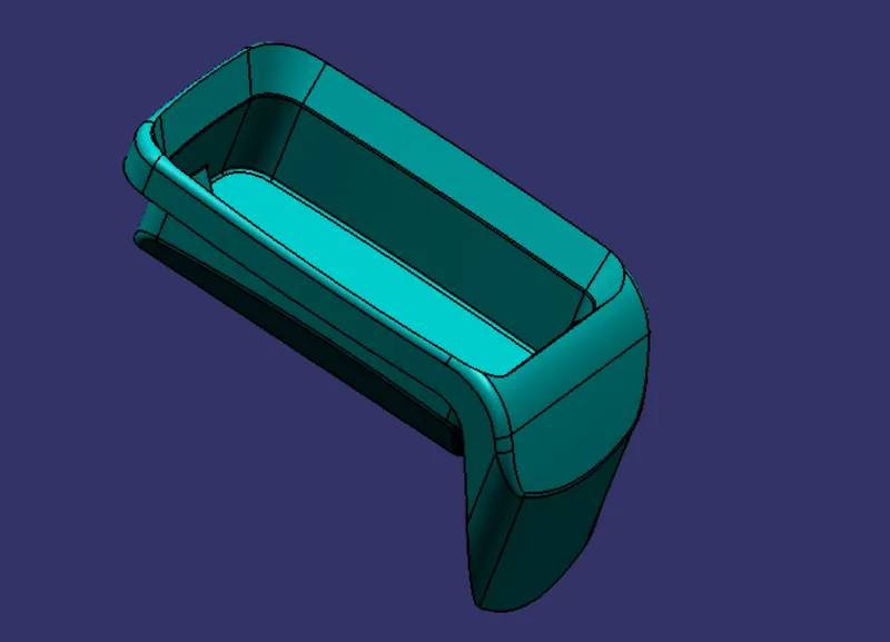
Class A surface of the coin holder.
DRAFT ANALYSIS:
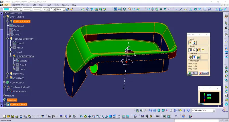
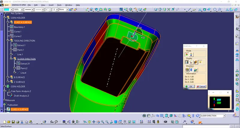
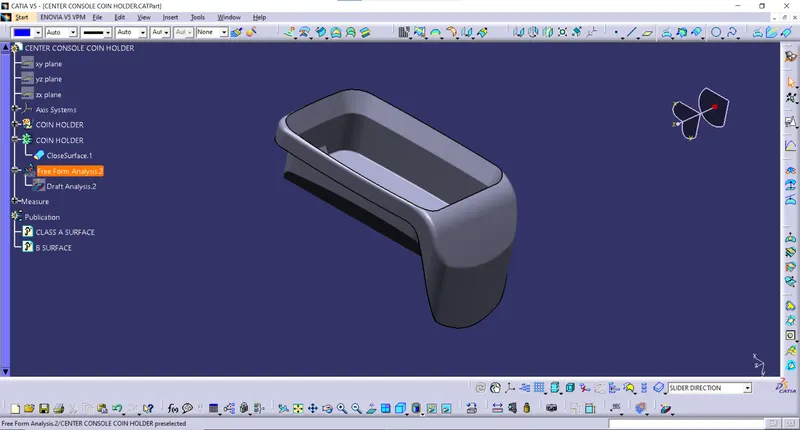
The draft analysis when carried out for this surface A, is undoable because of the inner bin walls and the outer walls are perpendicular and 0 draft has been provided. With compass method only a maximum portion of the surface cleared at the expense of a mere parallel rather perpendicular tooling direction which will have the core and cavity positioning an almost impossible task to carry out.
Hence, the tooling direction perpendicular to the bin is created and the slider axis drafts out the rearward of the stiffner and the side cut hole profile.
SLIDER TOOLING AXIS:
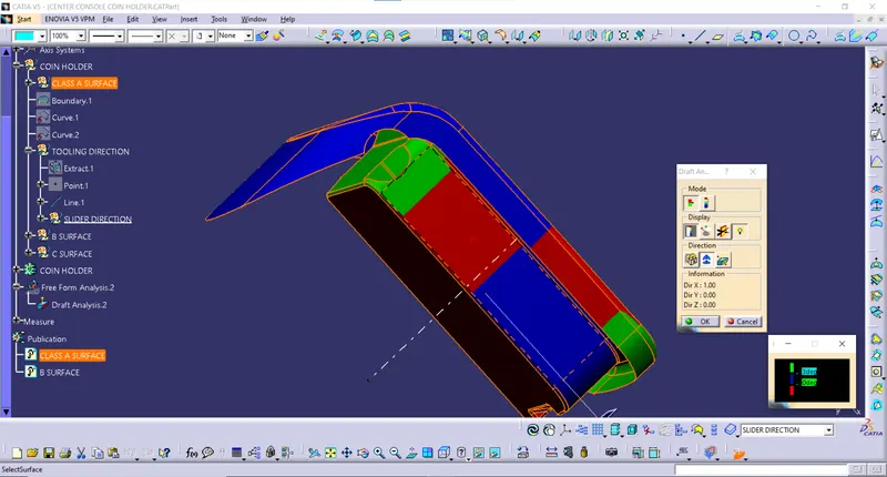
There is a requirement for slider direction to clear the side cut hole surface and at the rearward of the stiffner.
CLASS A ANALYSIS:
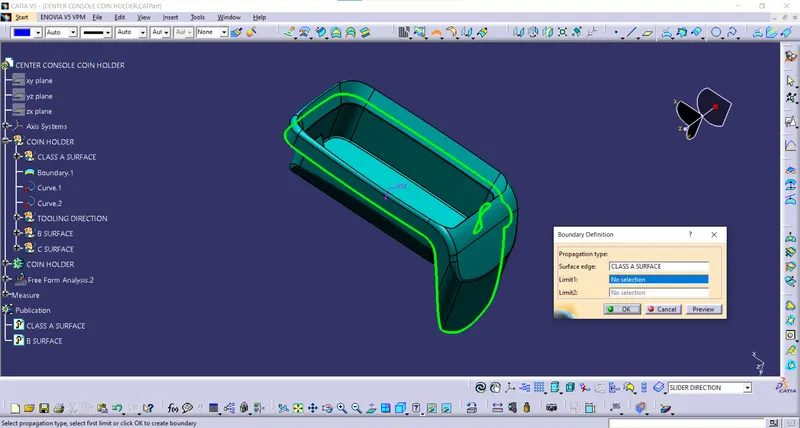
The given class has to be visually as well as with the commands to be inspected for the boundary and surface tangency. While making the boundary analysis there are two non connex boundaries can be seen
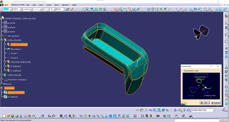
This can be separately extracted by the disassemble command and getting the two separate domains into the tree.
CLASS B SURFACE:
Intially, the side walls are extracted, untrimmed, extrapolated and given the offset value of the thickness, 2.5 mm.
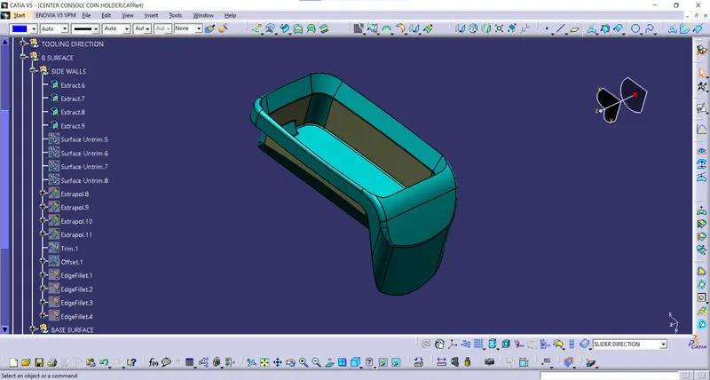
Once they are trimmed together, fillet definition is carried out.
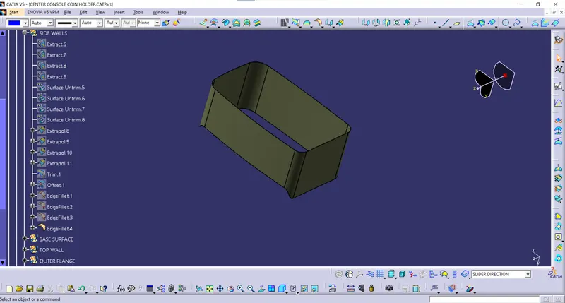
Now, the base, and its tangential inclined surface is extracted and trimmed together giving the offset.
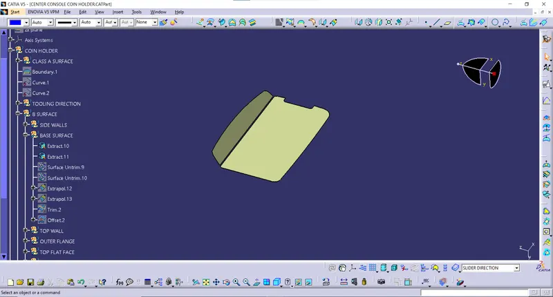
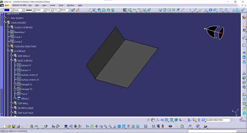
The stiffner profile is extracted and they are trimmed together with the base surface.
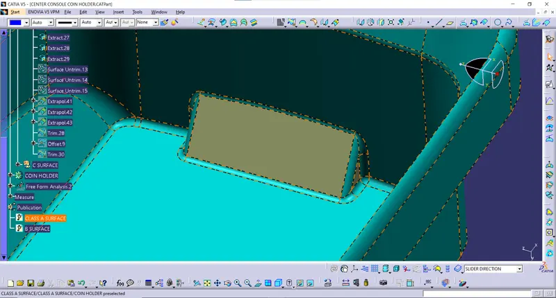
Then, the base surface and the bin walls are trimmed together.
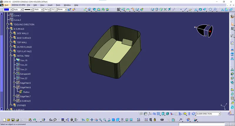
Now, the top walls are extracted.
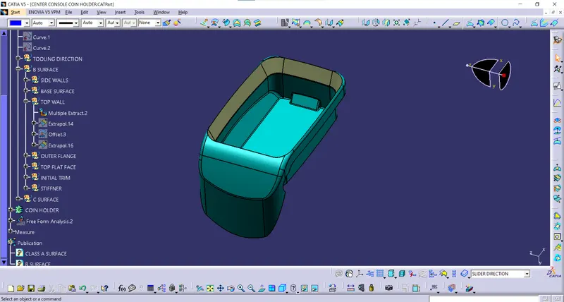
Then, they are extrapolated and given offset.
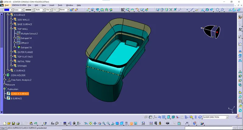
Outer flanges of the coin holders are extracted using multiple extract commands.
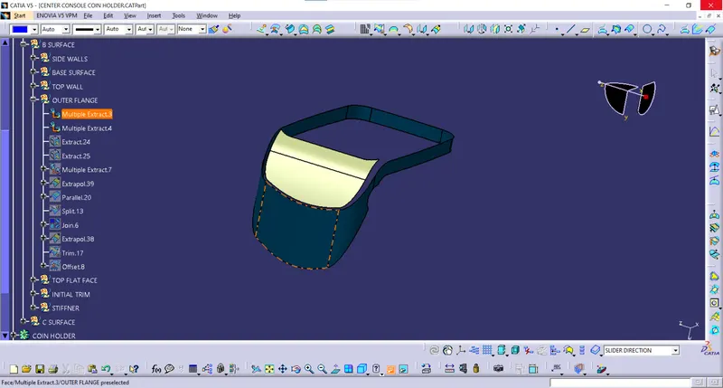
This portion cannot be extrapolated due to the upper edges intersection into the horizantal surface. Hence, they are untrimmed and extrapolated.
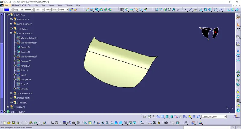
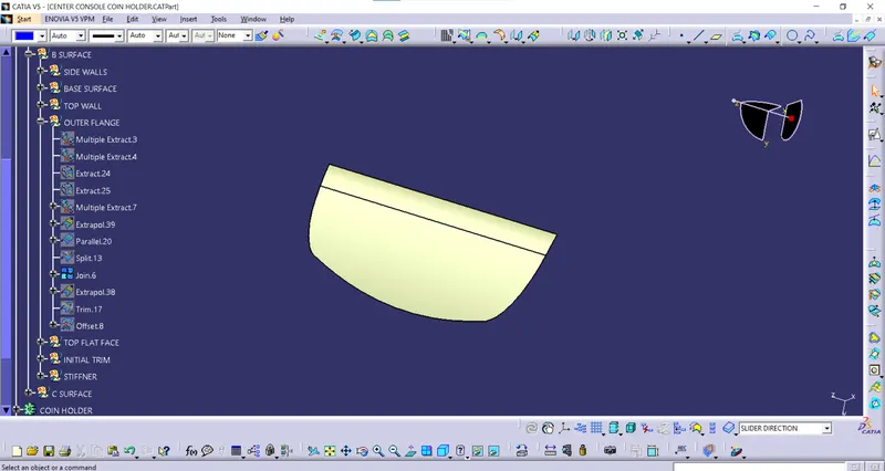
Once, then these surfaces are trimmed along with the top surface.
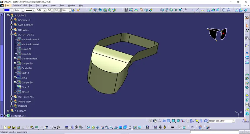
Above portion being trimmed along to the base surface and the walls.
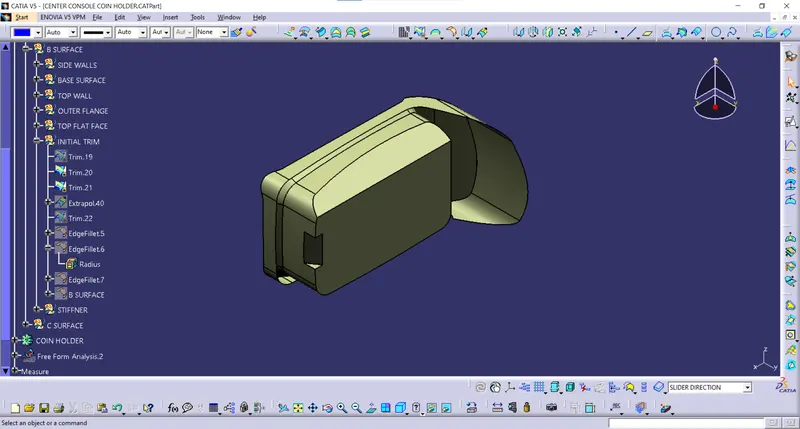
Fillets are given according to the A surface.
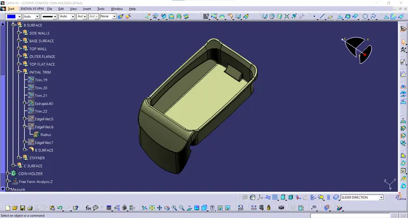
C SURFACE:
The walls of the surfaces B and A are not perpendicular but parallel to the tooling direction. Hence, they are closed by joining the outer walls.
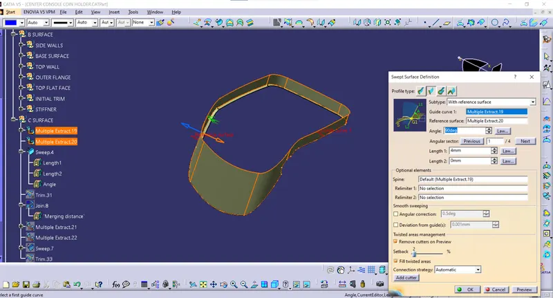
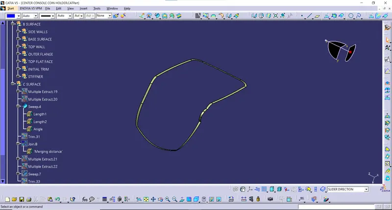
This surface then joined together by the trim command.
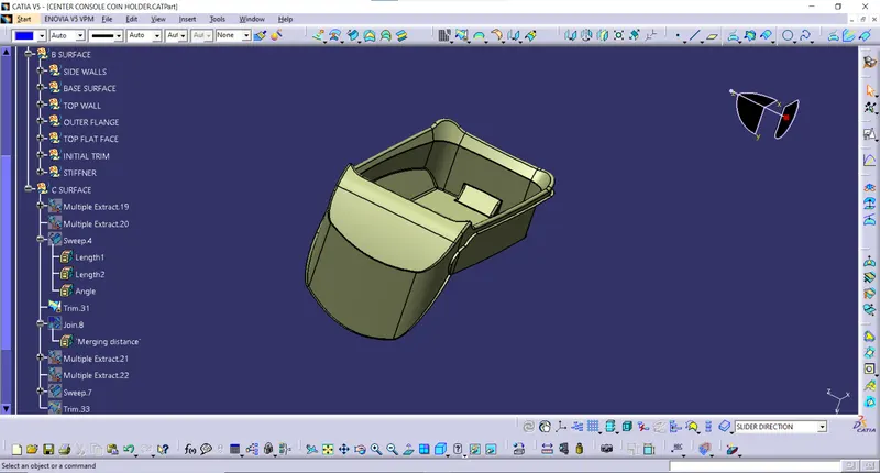
Which, then again joined together to the A surface.
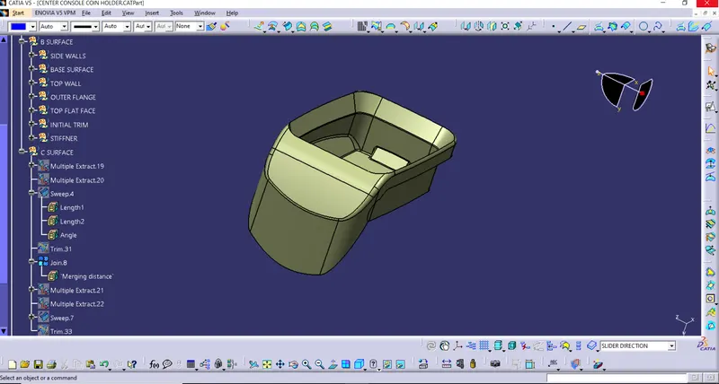
SOLID BODY:
Solid body of the same surface is provided in the part workbench.
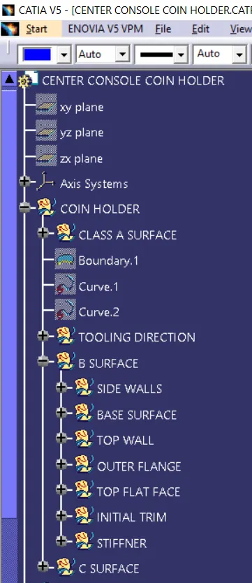
GEOMETRY TREE:
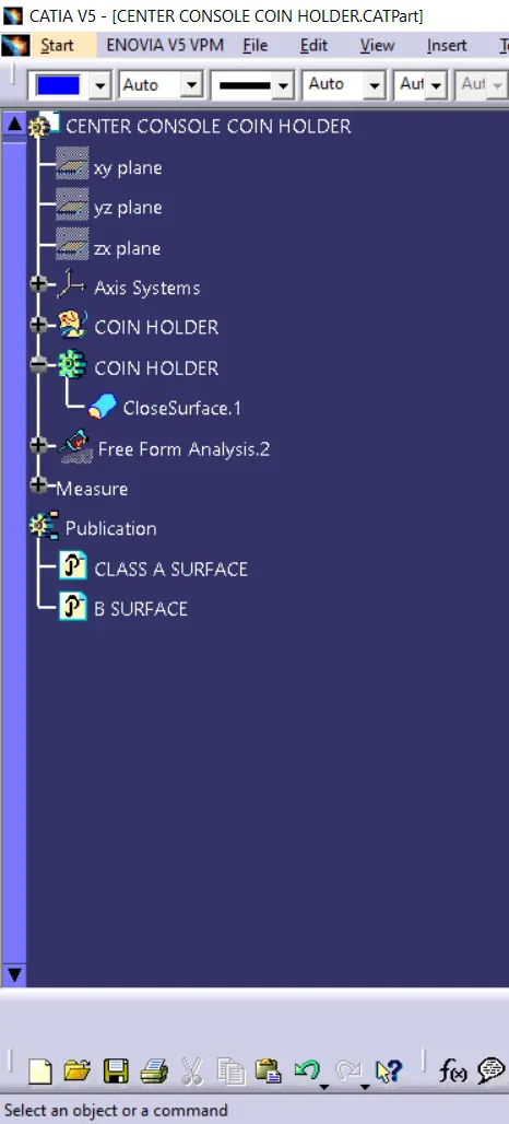
Part tree along with draft analysis