Week 8 - Challenge 4 - Coin Holder Design
Coin Holder
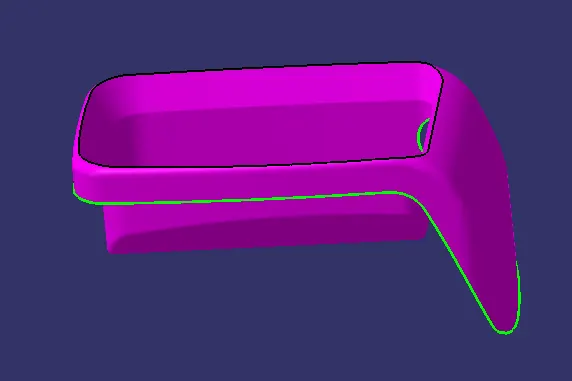
The First Step is Class A Surface creation. The surface are joined together using Join command to create class A, the created surface is then checked for any gaps and boundarries.
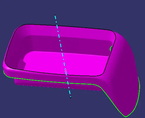
The next step is tooling axis creation. For this step a point is created at the centre of the bottom base of class A and a line is erected at the point using line command. this line is taken as the tooling axis (z- direction). Once the tooling axis is created the feature is published for ease of access from the tree sructure.
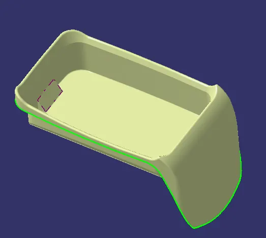
The next step is class B surface creation. This step is approached in different sections, each parts are extracted seperatly. The base side wall and top wall are extracted then untrimmed and extrapolated. Each part are worked on this approached and once extrapolated to a certain length they are trimmed with each other. once the surfaces are trimmed they are offsetted to a diatnce of 2.5mm from class A.
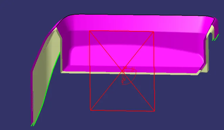
Once Class B is created the next step is the creation of Class C Surface. Since the tooling axis is normal to the base we are unable to create a sweep with respect to the tooling axis, Instead we extract the Boundary of class A and they are sweeped with an angle 90 deg to the reference surface.
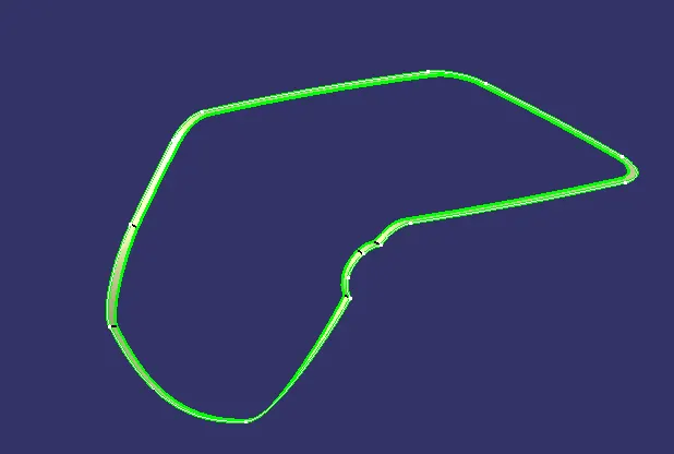
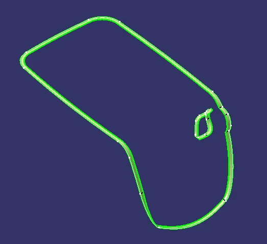
once the Class C surface is created they are trimmed with the class b surface to create a close surface.
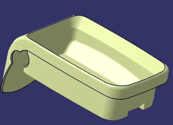
Once the surface is created the next step is to select the part desgin option and select close surface to create a part.
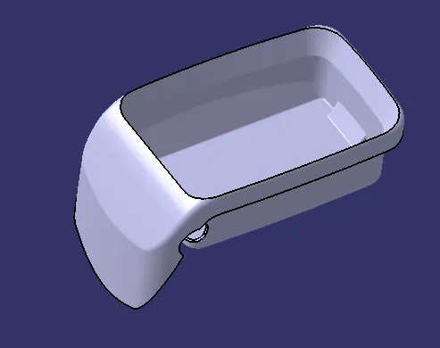
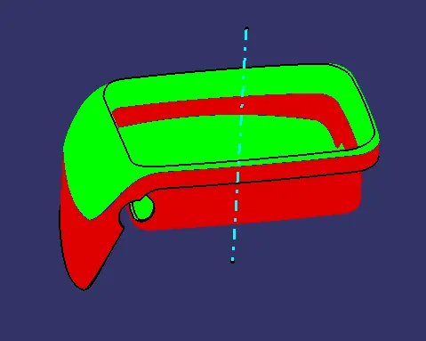
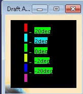
Once the part is created the next step is to do draft analysis on the created part body. click on Insert> Analysis > Feature draft analysis to obtain the draft analysis window, were the compass option is used to define the tooling axis once the compass is locked on to the axis by clicking on the surface we obatin the draft analysis with the colour code. The green are shows 3 deg draft on surface wereas the red denotes negative draft.
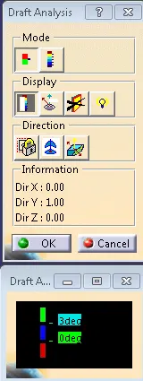
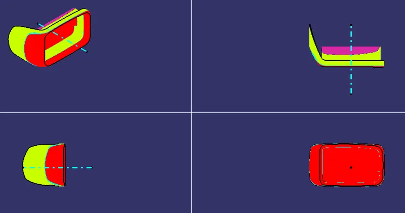
Different Orientations in Full Analysis mode is shown below.
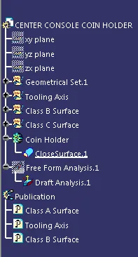
The Tree structure of the coin holder