Week 8 - Challenge 4 - Bumper
BUMPER DESIGN
AIM:
To create the bumper plastic component through the given Class A Surface and to perform draft analysis on the plastic component.
OBJECTIVES:
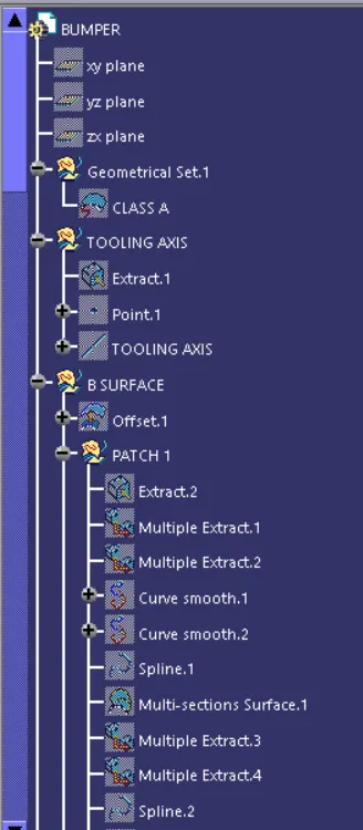
Create the Tooling Axis
Create the Class B and C Surface
Create the Close Surface
Perform Draft Analysis
SPECIFICATIONS:
Bumper Thickness = 3mm
Minimum Draft Angle = 3 Degrees
INTRODUCTION:
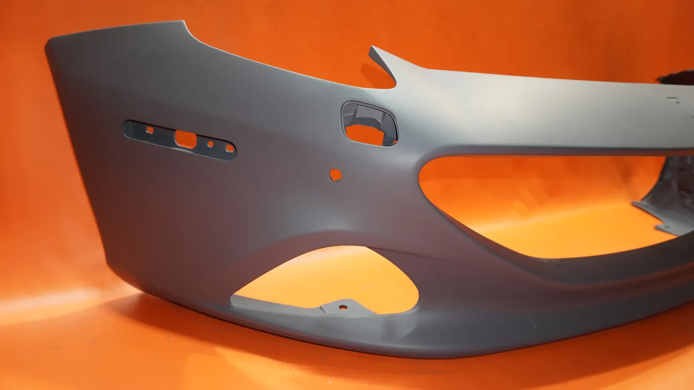
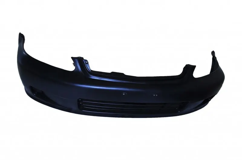
A bumper is a structure attached to the front and rear ends of a motor vehicle, to absorb impact in a minor collision, ideally minimizing repair costs. stiff metal bumpers appeared on automobiles as early as 1904 that had a mainly ornamental function. Numerous developments, improvements in materials and technologies, as well as greater focus on functionality for protecting vehicle components and improving safety have changed bumpers over the years. Bumpers ideally minimize height mismatches between vehicles and protect pedestrians from injury.
CLASS A SURFACE:
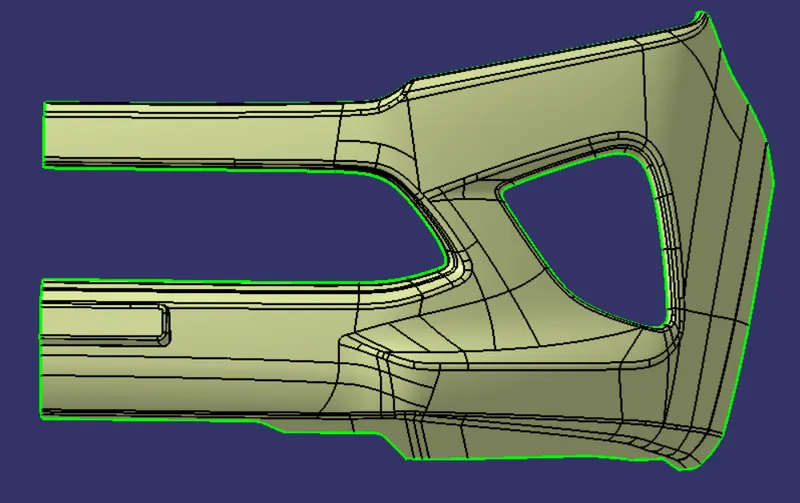
It is the aesthetic surface and the outer surface. The Class A surface is given as input to the plastic designer to create the plastic component.
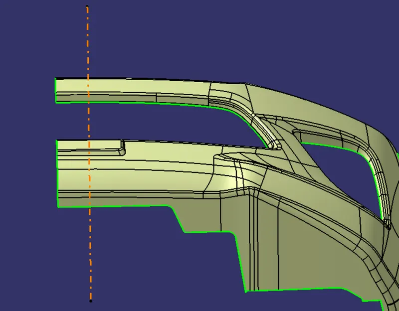
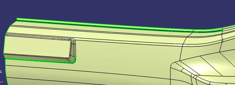
Inport the Class A surface and check for gaps using boundary in the given class A surface. Then Create a tooling axis to check the given surface is capable for drafting.
TOOLING AXIS:
It is the direction in which the core and cavity opens and closes. After the class A is imported check for possible irregularity, using boundary.
Extract a flat surface, create a point on the flat surface using on surface option. Create a line using point direction in the point on surface. The created line is the tooling axis, perform draft analysis on the class A surface using tooling axis.
DRAFT ANALYSIS:
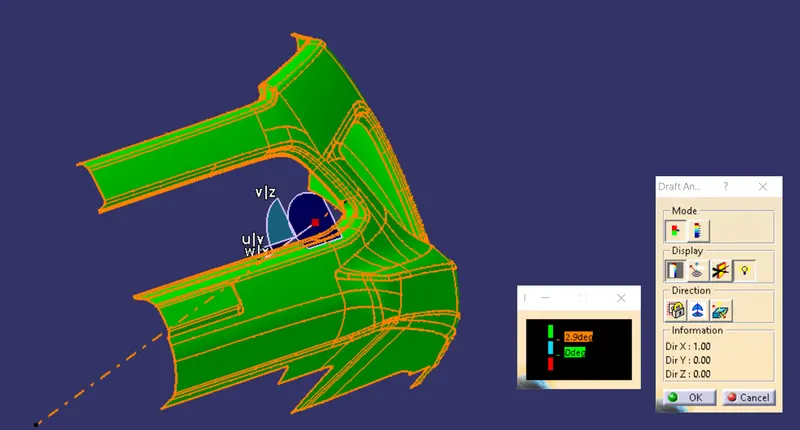
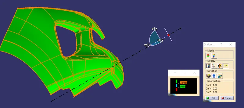
The draft analysis technique is used to analyze whether our part model created is manufacturable based on the draft condition applied. To perform draft analysis the view parameters are set to material mode.
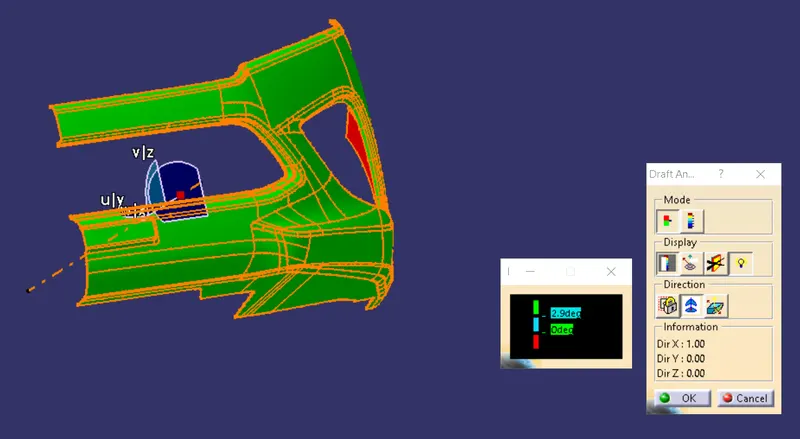
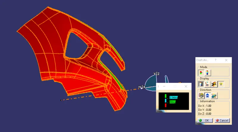
Then insert the feature draft anlysis select the axis system and drag the axis system to align and coincide with the tooling axis and lock the orientation.
This axis system defines the draft direction according to the tooling axis. Set the minimum value, here it is set to 3 degrees and it will be displayed in green colour. Now select the running point tool to measure the draft angle at various locations.
B SURFACE:
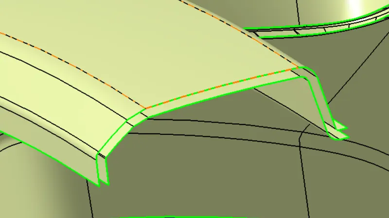
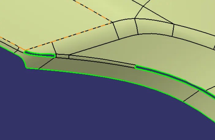
The offset from Class A surface is used to produce the class B surface. Offset the given Class A surface downwards to 3mm. There will be certain patches in the offseted surface, close all the surfaces using multi-section surface.
PATCHES:
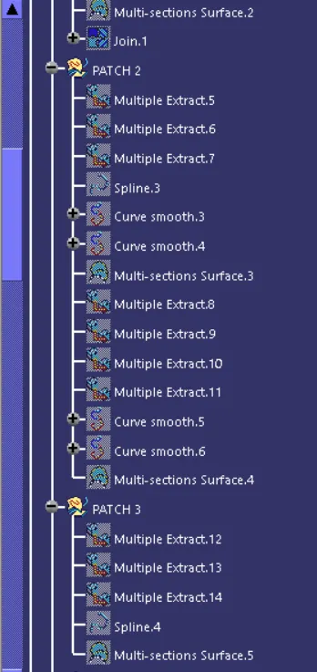
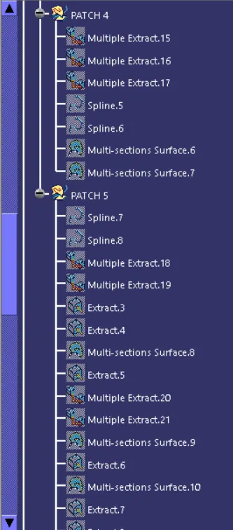
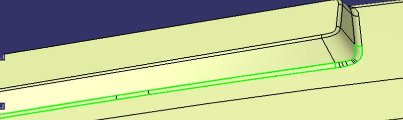
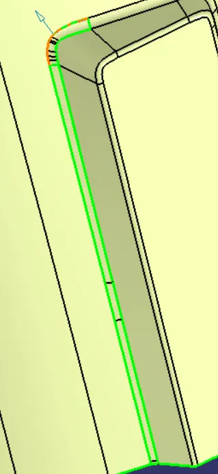
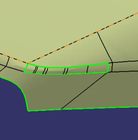
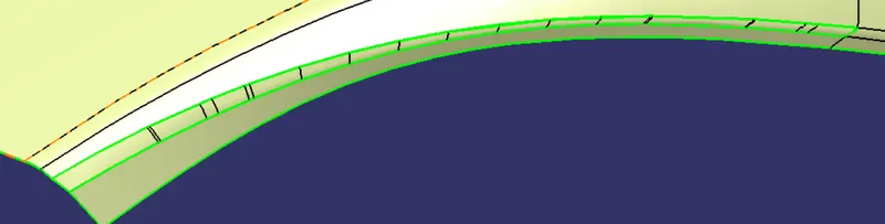
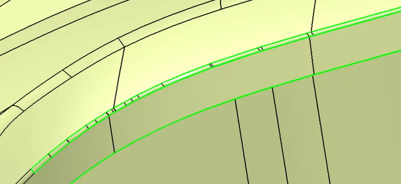
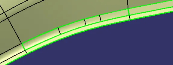
If there are four surfaces on the outside and there is surafce missing on the inside, Extract all the other sides and do a multi-section surface using the four surface to create a surface to close the patches.
If there are three sides of surfaces is present and one side is missing, Extract the edges of three sides and draw a spline on the side where no edges is present. Do a multi-section surface with spline and edge as input and others edges as guide for the surface.
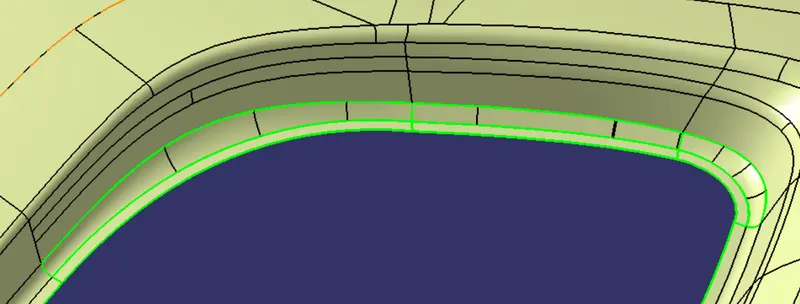
COMMANDS USED FOR PATCHES:
Extract
Multiple Extract
Curve Smooth
Multi-sections Surface
Spline
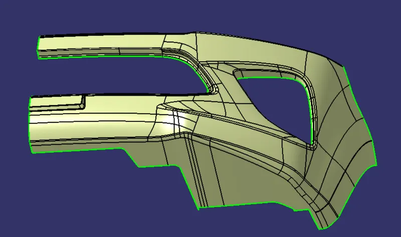
CLASS B:
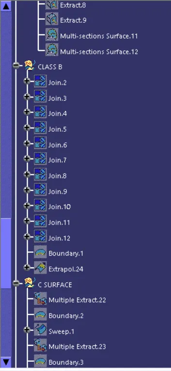
After closing all the patches join them together to get the final Class B Surface.
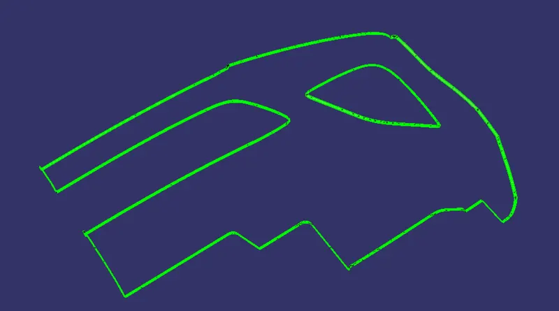
CLASS C SURFACE:
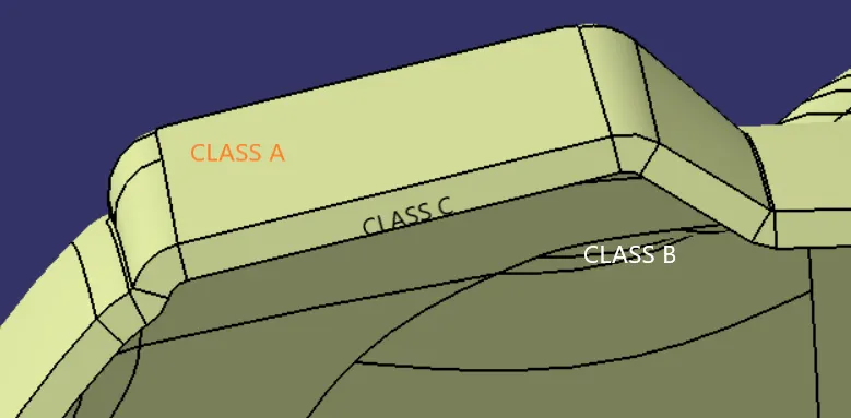
This is the surface that connects the class A and B surfaces together. After joining surfaces together check the draft analysis on the final component, convert the component into a closed surface.
Using multiple extract, extract the surfaces on the boundary and extract the boundaries. split the boundaries and do sweep on them seperatly based on reference surface option.
Join all sweeps together and perform sweep seperatly on the inner boundaries. join all the sweeps with the class A surface.
CLASS A AND C:
Join the class A and C together and trim the join with the B surface.
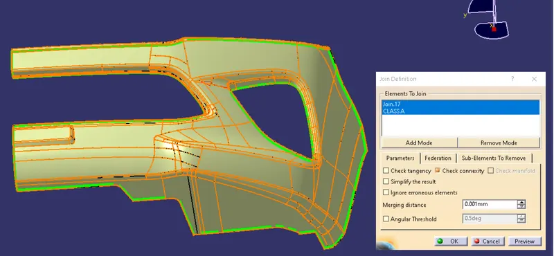
FINAL TRIM:
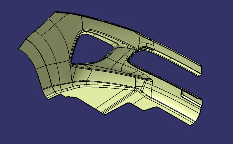
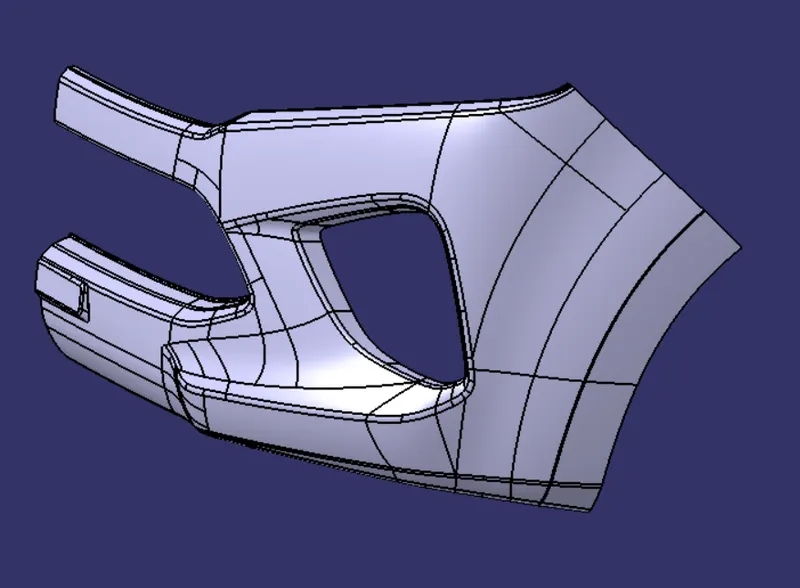
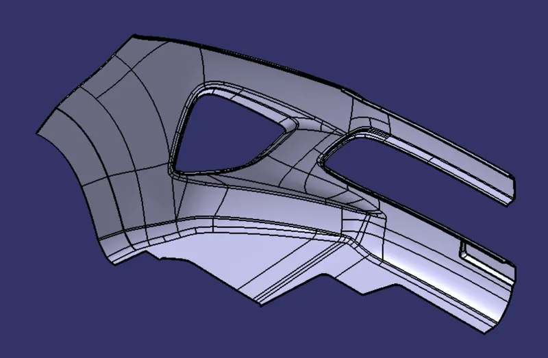
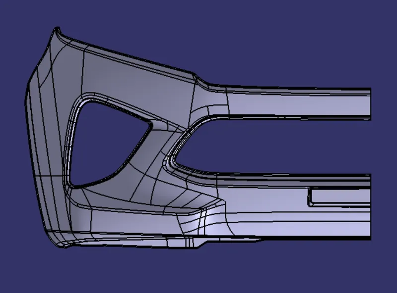
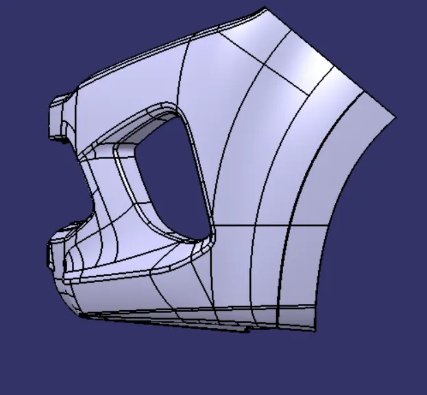
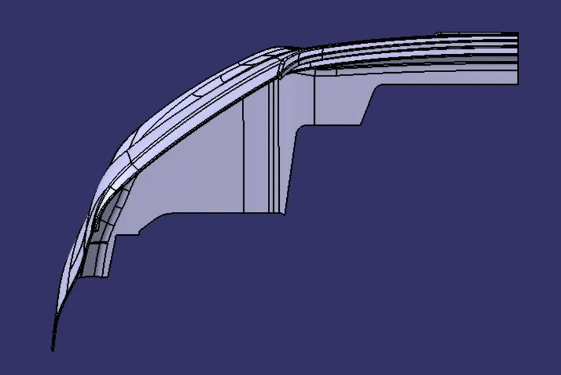
Trim the above joined surface with the Class B surface to get the final plastic component.
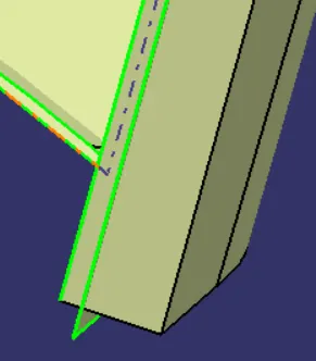
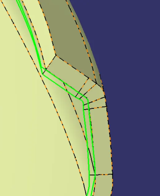
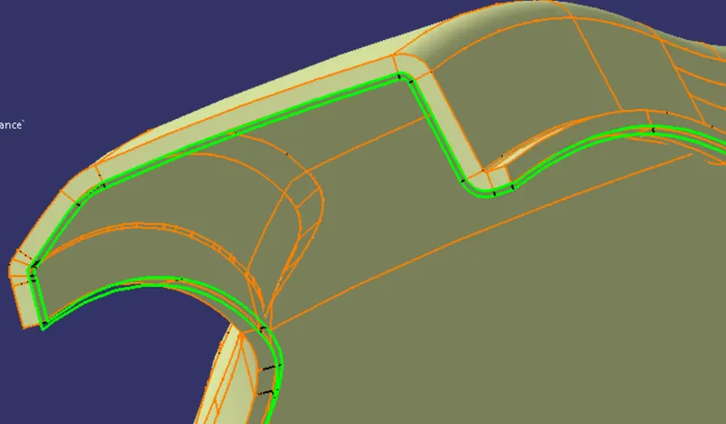
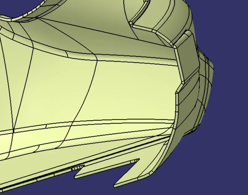
FINAL PLASTIC COMPONENT:
DRAFT ANALYSIS:
Perform Final Draft Analysis on the plastic component. Enable the tooling axis and enter the axis system on the tooling axis and analyze the draft on the surface.
CLOSE SURFACE:
Import the final component on the part workbench, defines the part body and do close surface operation on the final trim.
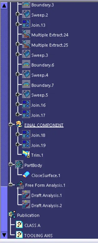
TREE STRUCTURE: