Week 8 - Challenge 4 - Bumper
AIM
To create the Bumper Plastic component through the given Class-A surface.
REPORT
1. Creation of tooling axis
- First we check the connectivity of the given class A surface using boundary or join command.
- We study the surface at all axis and decide on the best possible side to create tooling axis.
- First, let us extract a small surface from class A through which the tooling axis passes.
- Create a point on the extracted surface at its center.
- Create a dummy tooling axis passing through the point along x axis.
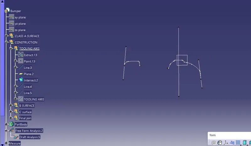
- Create a plane normal to curve.
- Select the intersection option and create an intersection on class A with the plane.
- Once the intersection is created, identify the two surfaces which are problmatic while tooling.
- Draw line on both these surfaces using line command.
- Again using the bisecting lines in the line command, a new line is formed which is our tooling axis.
2. Draft analysis on Class A surface
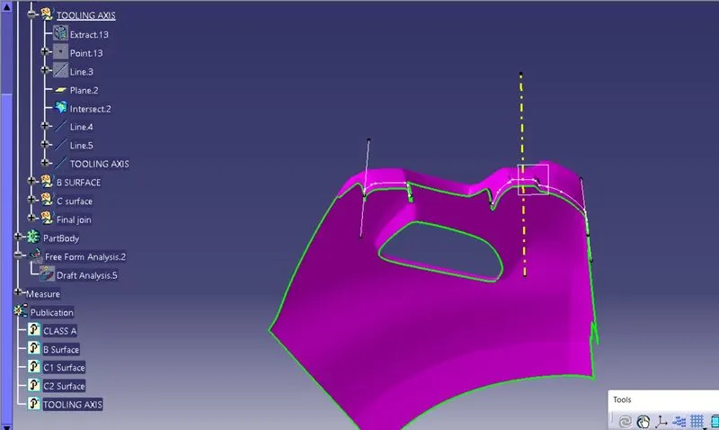
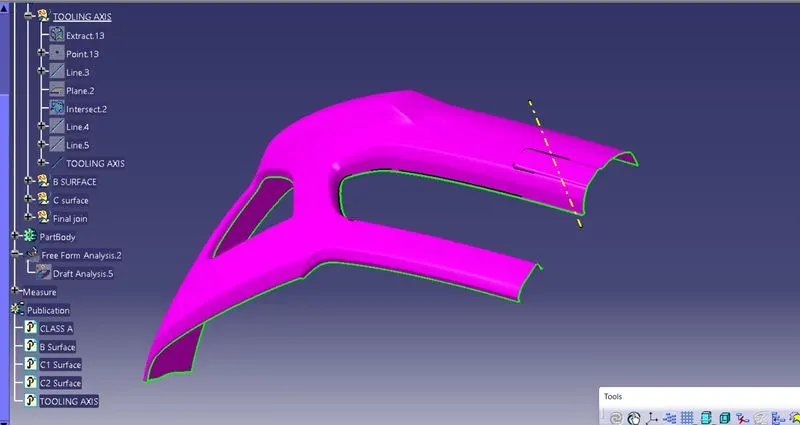
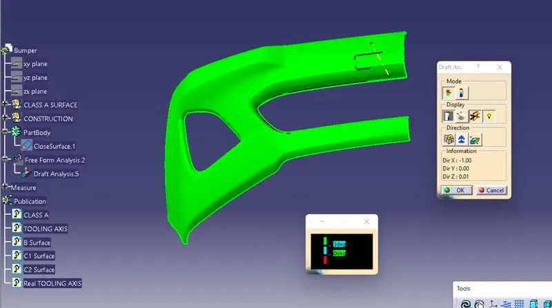
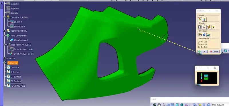
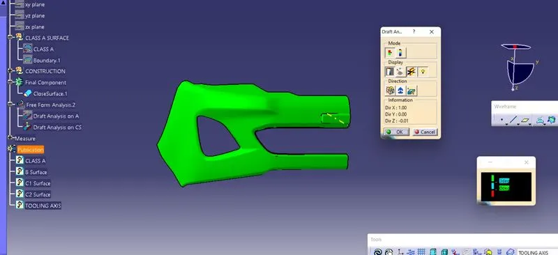
- Once the tooling axis is created, we conduct draft analysis on the class A to verify thr tooling axis.
- Click on thr draft analysis icon.
- Select the compass and place it on the tooling axis.
- Click anywhere on the surface, draft analysis occurs.
- From the results we can see that its completely in green colour.
- This means that there is a positive draft of 3 degrees which is good.
3. Creation of B surface
- First, offset the A surface inwards by 3mm.
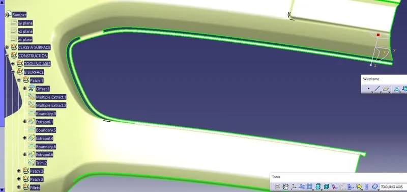
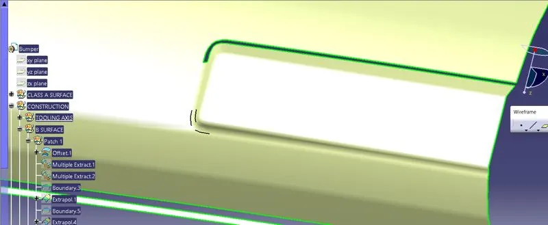
- We can see lot of patches in the offseted surface.
Patch 1
Patch 2
Patch 3
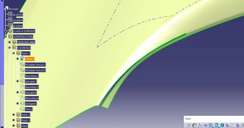
- So we try to fix all those patches one by one.
- Lets take patch one.
- Using multiple extract we extract all the patchy surfaces using complimentary mode.
- Then again using multiple extract, we extract the outer surface which we require to connect it to the main surface.
- Using the extrapolation option we extrapolate the extracted surface to a certain distance.
- Then we extrapolate the main body till it intersects the above extracted surface.
- Using trim we trim the unwanted surface and gets the patchy surface repaired.
- We then apply edge fillets on them.
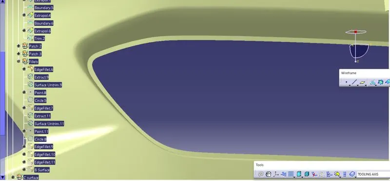
- For fixing patch 2, we extract the patchy surfaces.
- Unrim these surfaces.
- Extrapolate them till they intersect.
- Trim all of them.
- Extrapolate the main body till it intersect the above body
- Trim these two surfaces and apply edge fillet to repair these patches.
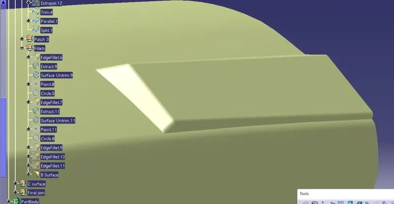
- Similarly what we have done for patch 1, same steps are repeated for patch 3 to form the B surface.
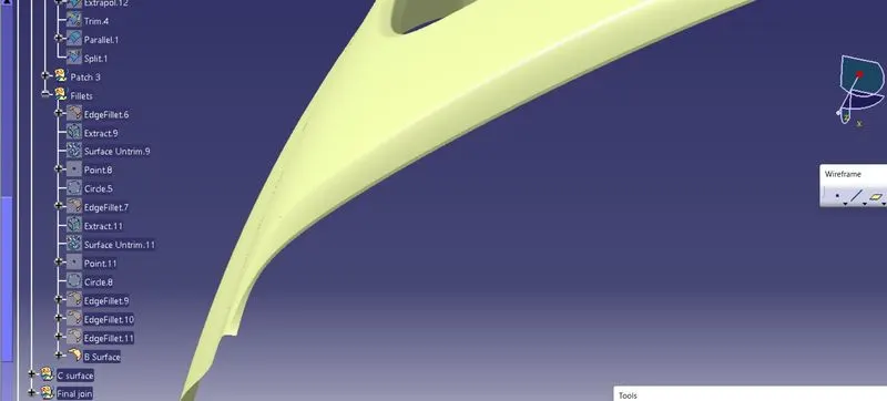
B surface -
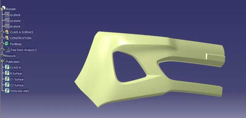
4. Creation of C surface
- To create C surface, we take boundary from one sharp corner to another.
- Apply sweep command with reference surface.
- Almost 7 sweeps are created.
- All those sweeps are extrapolated and trimmed to form a single surface.
- Similarly we apply sweep to the inner section also.
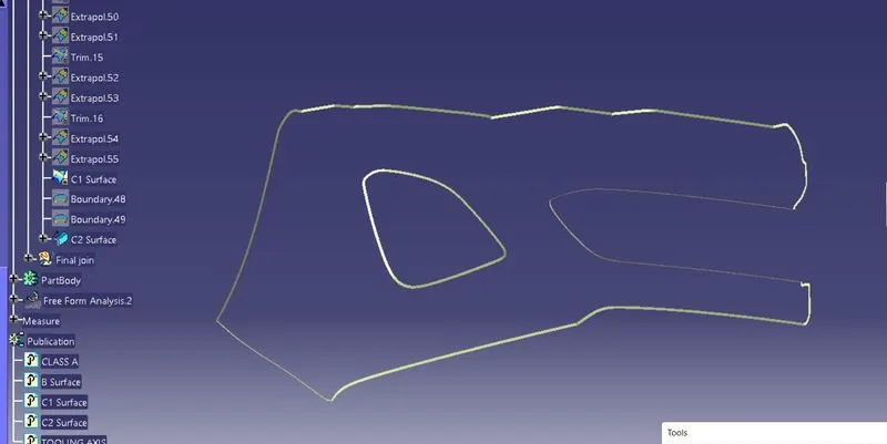
5. Final Join
- Join Class A and C surfaces together.
- Extrapolate the boundaries of B surface.
- Trim the A+C surface together with B surface.
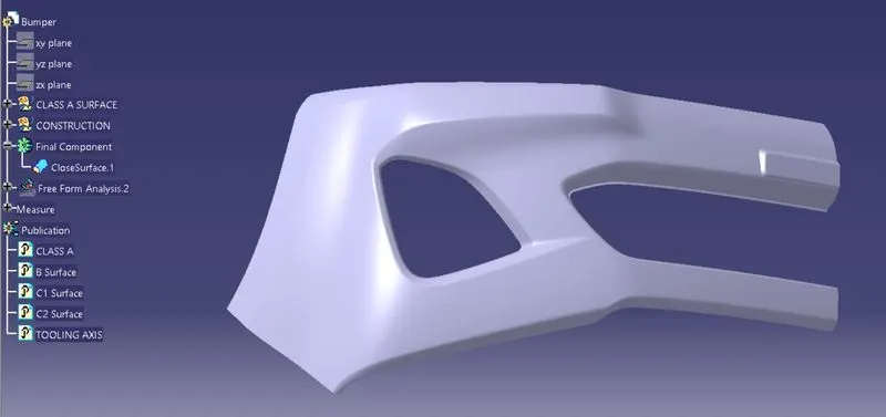
6. Closed surface/Final component
- Open part design.
- Select closed surface option and apply it on the final join.
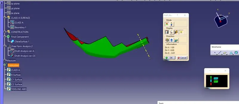
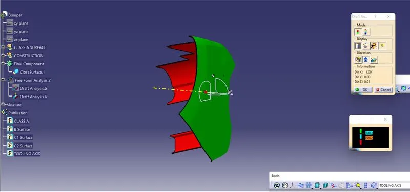
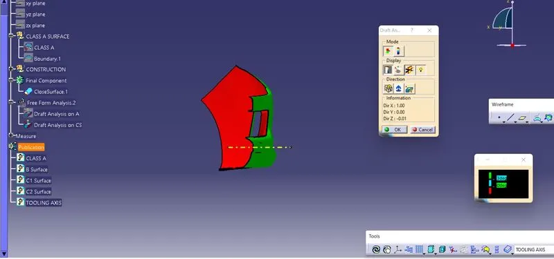
7. Draft analysis on Final component
- Repeat the same steps for draft analysis as done on Class A.
- We can see green for core side and red for cavity.
- Hence it passes the analysis.
RESULTS
1. ISOMETRIC VIEW
2. FRONT VIEW
3. SIDE VIEW
4. TOP VIEW