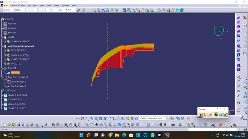
Week 8 - Challenge 4 - Bumper
Class A Surface:
The Class A surface is gives is shown in below image:

Procedure:
Step 1 : Connectivity of the Class A Surface
- Check the connectivity of the Class A Surface that is to check that there is no gap between the components using the Join command or by visual inspection or also by using the Boundary Command.
Step 2 : Tooling Axis
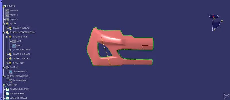
- The Tooling Axis is created using Bisecting Line Method.
Bisecting Line Method:
In Bisecting Line method is that the possiblities or clearance is checked along the direction using the intersection of surfaces along the axis on the plane of the Class A surface and the two lines is created on the intersections walls that is along the inclined walls of the intersections. Then the line is created by using bisecting line option in line command using the two lines and the point created and that line is Tooling axis.
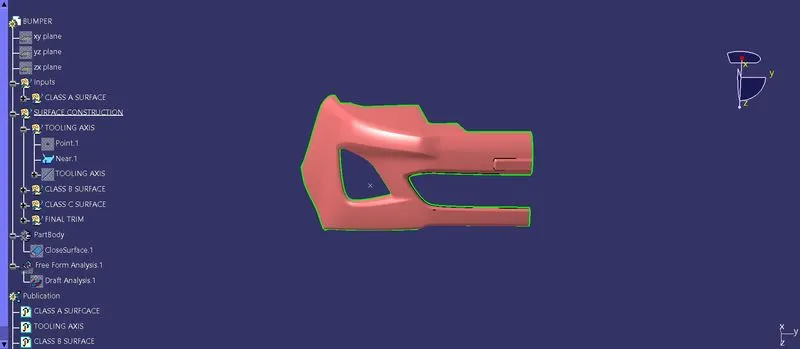
- For Creating tooling axis we create the point. The image of point is shown below
- We directly created a line using Class A surface and point as reference and the line is our tooling axis. The image below shows the Tooling Axis.
Step 3 : Draft Analysis
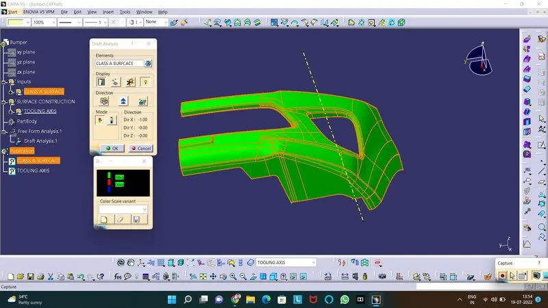
- Draft anlaysis is done based on the tooling axis. Draft analysis is used to check the Class A is maintained with minimum draft angle of 3 degree.
- The Compass is used define the Draft direction.
- The green colour shows that the minimum draft angle is provided otherwise blue color is shown to the surface. The image shows that draft analysis of the Class A surface with color scale variant.
Step 4 : Creating Class B Surface
- We first Offset the Class A surface with 3 mm which is given as thickness.
- Check for any discontinuity or gap between the joints or boundary is figured out in the offseted surface.
- If any any then by using Multiple extract, Multi Sections Surface, Sweep are used to fill the gap.
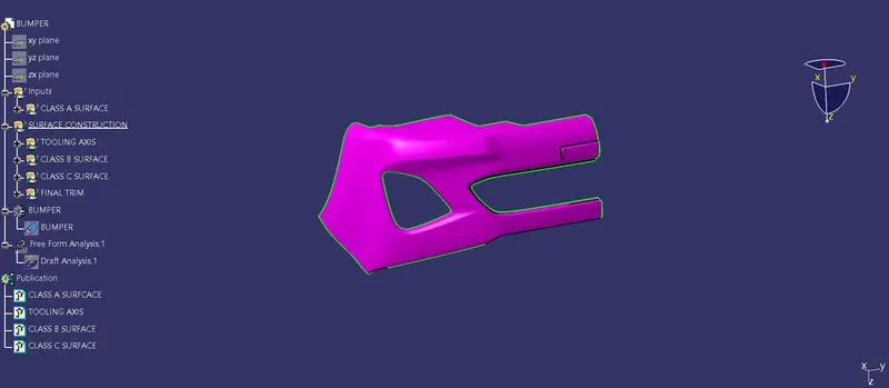
- Thus the Class B surface is created. The image shown below is Class B Surface.
Step 5 : Creating Class C Surface
- The Class C surface is the connection between Class A and Class B surface.
- Then the boundary is extracted using Multiple Extract command or Boundary command.
- Then these extracted surface is Swept using Sweep command with reference surface option is used.
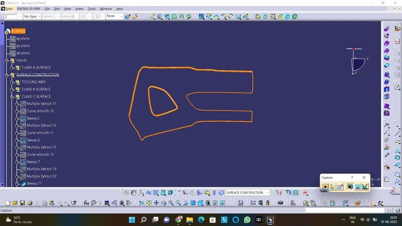
- Thus the Class C surface is created. The image shown below is Class B Surface.
Step 6 : Final trim to obtain Bumper Plastic component
- The last step is triming the Class c surface with the Class B surface and then joining the trimed surface with Class A Surface.
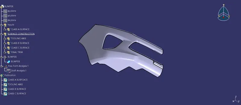
- Then the obtained surface is converted into solid using Close Surface and thus the final Door Trim Plastic Component is obtained. The image is shown below is Bumper Plastic component
Screenshots of the solid model:
Isometric:
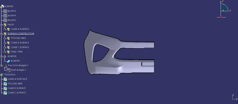
Front View:
Back View:
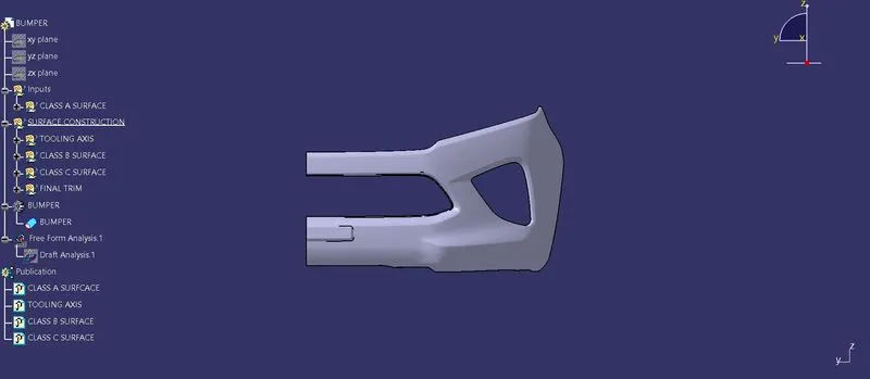
Side View:
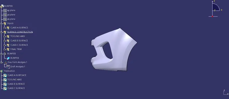
Top View:
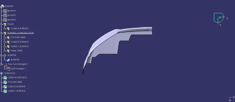
Draft Analysis of the Solid:
- Draft analysis is used to check the solid component is maintained with minimum draft angle of 3 degree.
- The Compass is used to define the Draft direction.
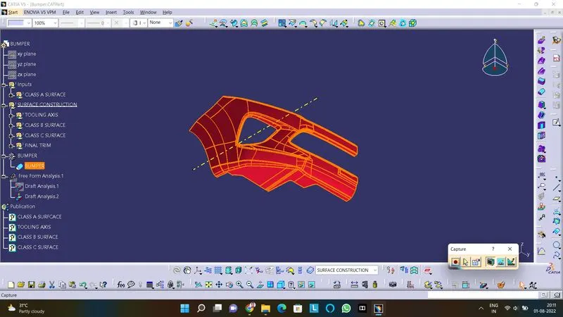
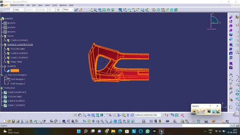
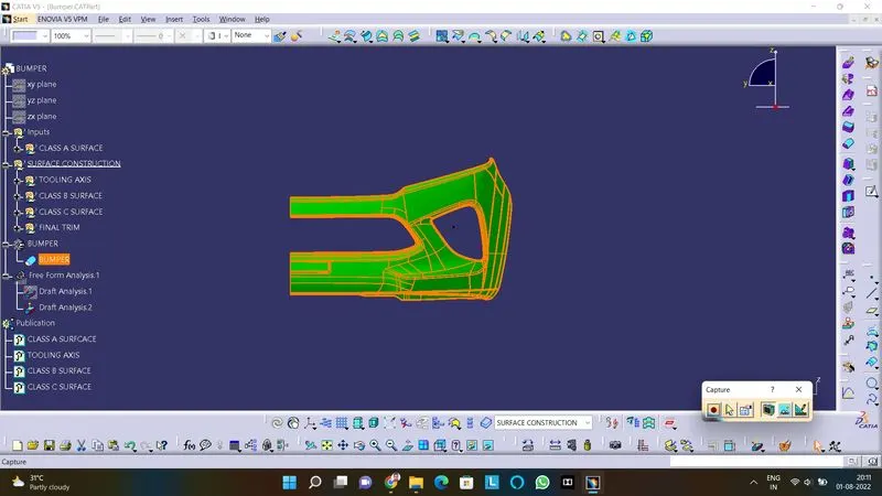
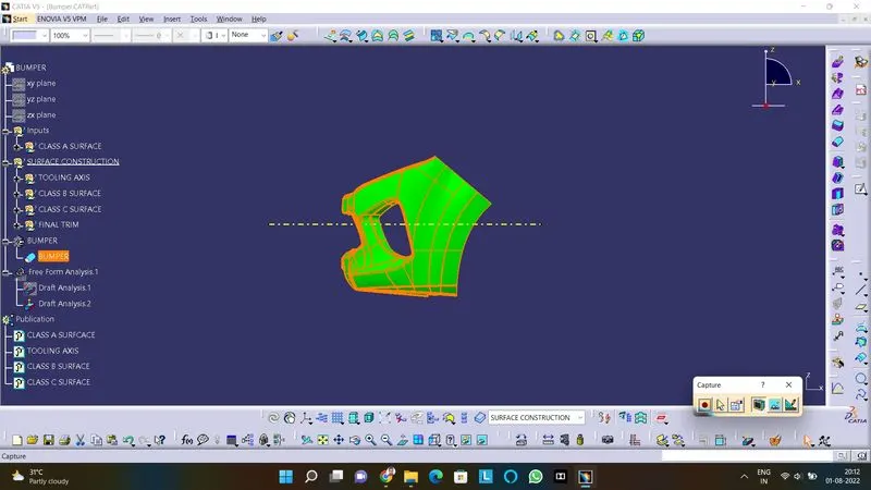
- The green colour shows that the minimum draft angle is provided otherwise red color is shown to the solid. The image shows that draft analysis of the solid with color scale variant.
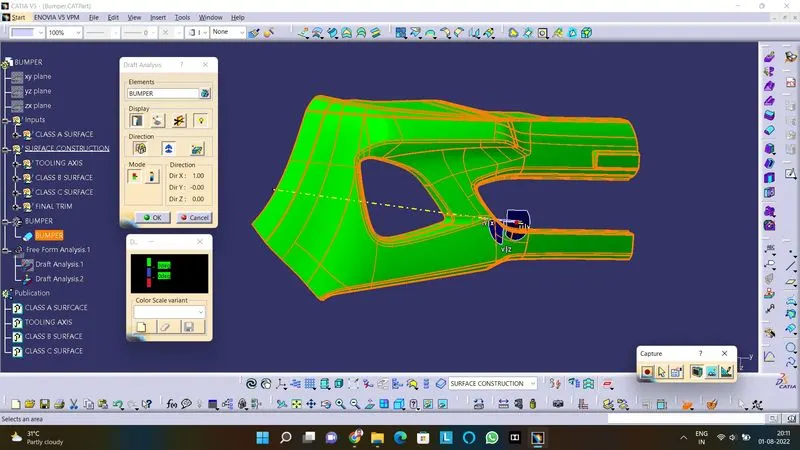
Screenshots of the solid model with the proper color code of the draft angle in various orientations:
Isometric:
Front View:
Back View:
Side View:
Top View: