Week 8 - Challenge 4 - Bumper
OBJECTIVE
Create the Bumper Plastic component through the given Class-A surface. To begin with, the tooling axis for the given Class-A Surface should be created meeting the requirements of the draft angle and at the end perform the Draft analysis on the model.
REQUIREMENTS:
Software Knowledge about CATIA V5.
PROCEDURE
Open the given class A surface file.
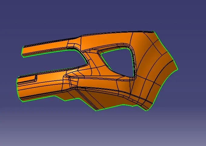
Tooling axis creation
The tooling axis direction refers to the direction in which the mould opens and shuts. Before defining the tooling axis, make sure the surfaces are connected and that there will be no gaps between them. Please make sure to place the tooling axis on a surface with a hole or one that is flat when building a tooling axis. In order to build the dummy tooling axis using the intersect method by creating a bisecting line, first create a point in the centre of the base surface using the point on the surface command. Then, create an intersection for the surface and extract the reference lines.Draw lines that are aligned with the extracted lines using the line command, extending them to the necessary length.
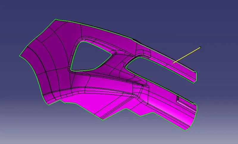
DRAFT ANALYSIS OF CLASS A SURFACE
To perform draft analysis, click on Insert >>Analysis >> Feature Draft Analysis.
To tackle this issue, CAD engineers uphold a common design rule for plastic moulds or dies, which ensures that there are no issues with ejecting plastic components. Therefore, every plastic component is designed with a minimum of 3 to 10 degrees of draft angle.
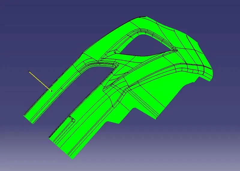
Draft analysis is performed on the given Class-A surface, and it is clearly observable that there is no negative draft on the surface.
CLASS B SURFACE
Extraction of the Class A surface without the fillets, extrapolation of the fillets to link them, offset of the surface to 3 mm thickness, and formation of the Class B surface.
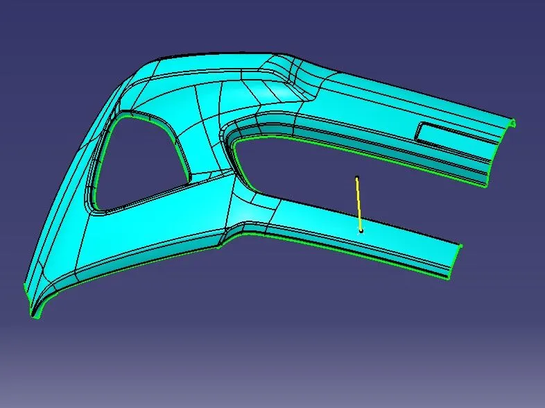
CLASS C SURFACE
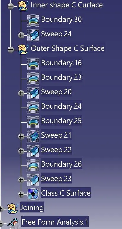
By extracting the boundary of the class - A surface, the surface required for the class - C is obtained, using the smooth curve option a smooth surface can be obtained by sweeping the line towards the direction of the tooling axis.
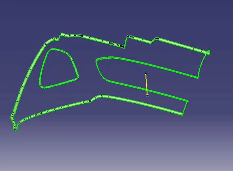
FINAL OUTPUT
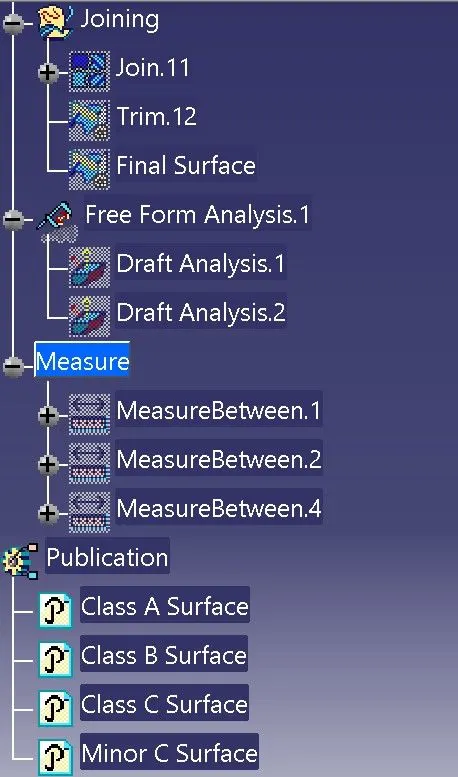
Join Class A and Class C surface using join command and make sure there's no gap between and we can check using boundary command for the gaps.
Then trim the joined A and C surface by B Surface to obain the final surface.
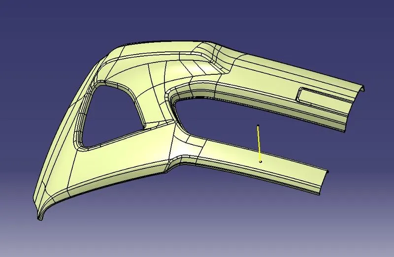
Open it in part file and use closed surface command to turn the final output into manufacturable product design.
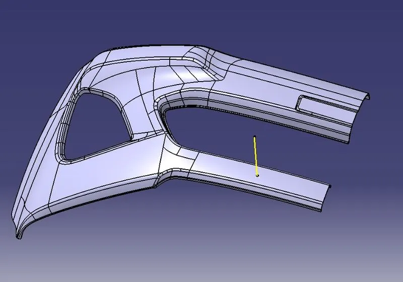
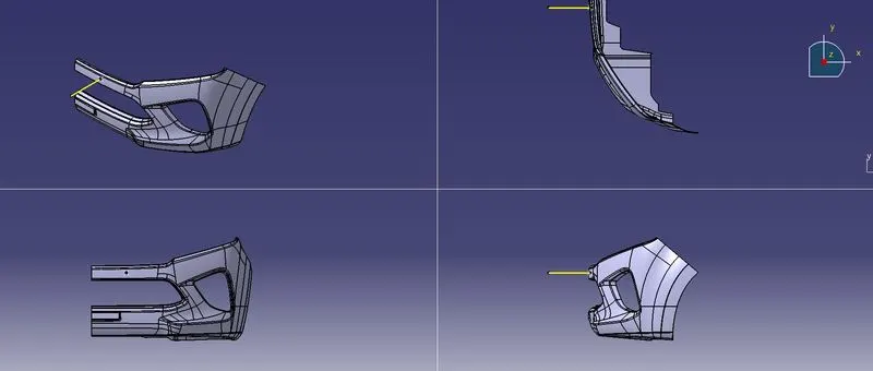
DRAFT ANALYSIS FOR FINAL OUTPUT
Go to the Direction block in the draf analysis toolbar and select the "Use the compass to set the new current draft direction" option to align and fix the compass to the tooling axis (or just click on the compass symbol). Bring the compass to the surface at this point, align it with the class A surface's tooling axis, and then click the lock icon next to it in the direction block. We can complete the draught analysis process by clicking "ok" on the toolbar for draft analysis.
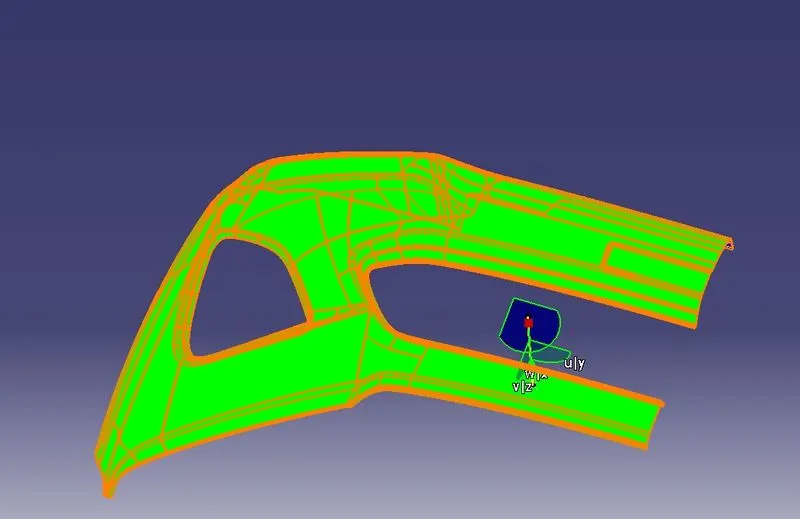
The Draft angle 2.9 was given to the final out come and it has passed without any errors.
FEATURE TREE FOR MODEL
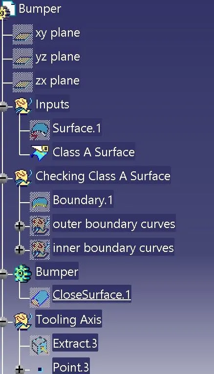
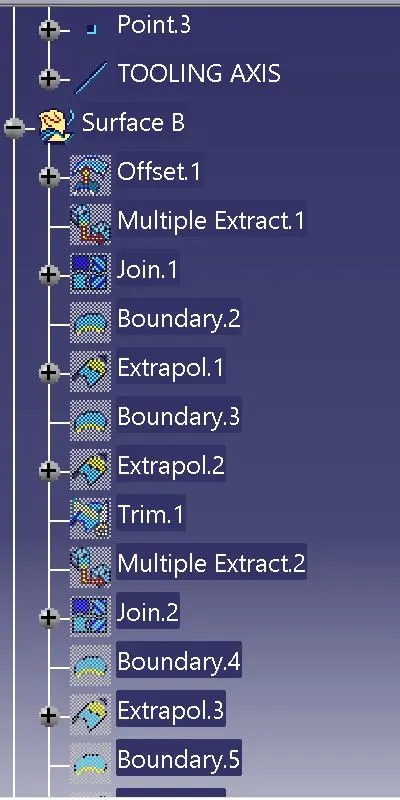
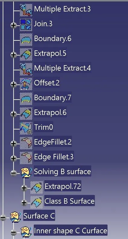
CONCLUSION
Thus the Bumper Plastic component through the given Class-A surface is completed, the tooling axis for the given Class-A Surface is created, meeting the requirements of the draft angle.