Week 8 - Challenge 4 - Bumper
BUMPER DESIGN:
The thickness of the component is taken as 2.5 mm.
Tooling axis: -
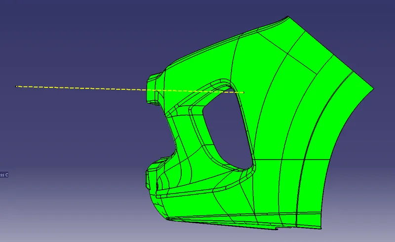
By observing the bumper, it can be said that the shape of bumper is complex. However, the bumper Class A can be said to have its entire surface along a general mean plane which is along its length. In general, for the bumper, any face can be selected to be the reference plane for the tooling axis. Later the selection can be confirmed by performing the draft analysis.
The face near the front of bumper Class a is selected and extracted, a point is created in the middle of the plane which is used for the reference for tooling axis. Tooling axis is created as a line normal to the extracted surface.
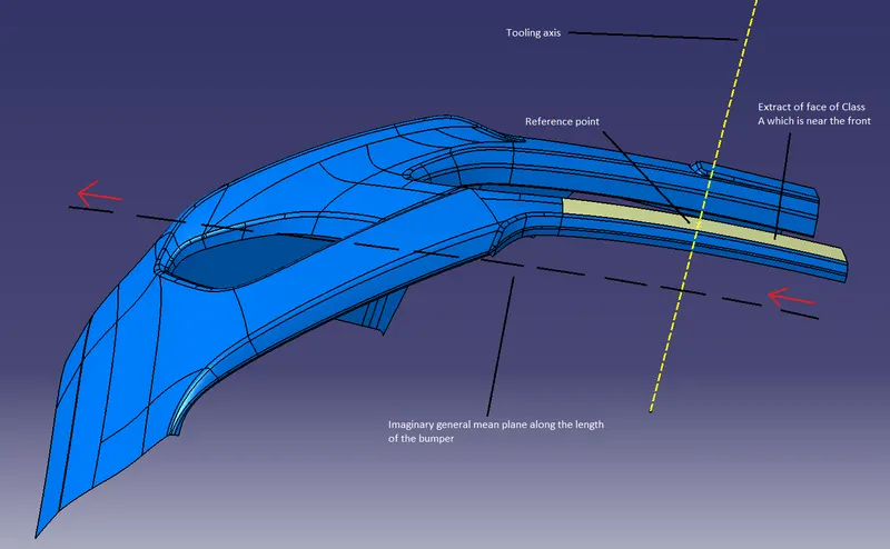
Tooling axis can also be created by bisecting method by using two faces of parts which are protruded along the length. With the surface and point as described above an axis system can be created and intersection of Class A with a plane can be done. By this, an intersection curve will be created and with the faces which are adjacent to face described in above method, two construction lines can be drawn with the help of intersection curve. These construction lines can then be bisected by a line which will be tooling axis. The tooling axis obtained by this method and previous method will be in the same direction.
Draft analysis of Class A and confirmation of tooling direction: -
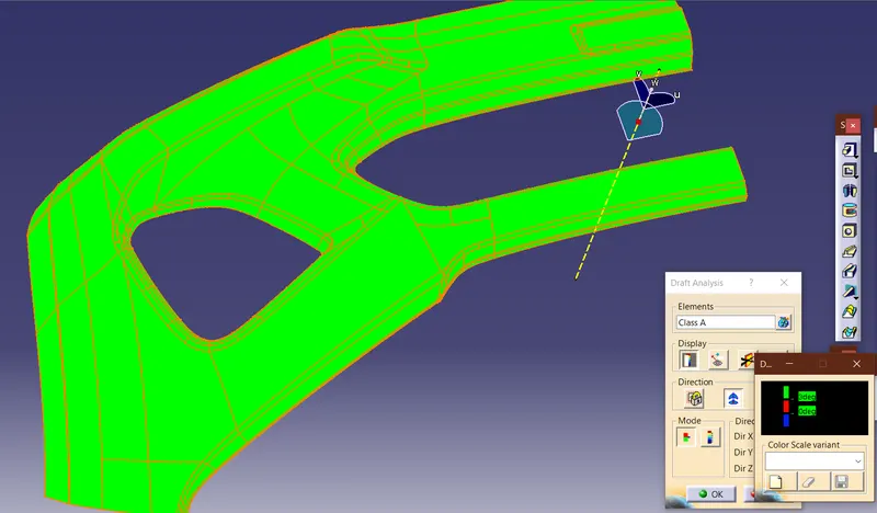
As we can observe from the results of draft analysis that all faces of Class A are green, which means that all the faces of Class A have draft greater than 3-degrees. This result also confirms that the tooling direction which was obtained earlier is correct.
Class B surface: -
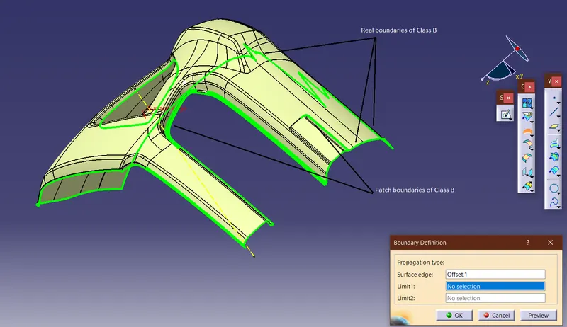
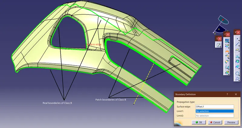
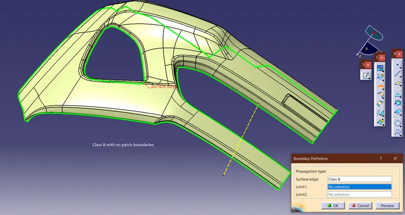
Since the bumper has an imaginary general mean plane i.e., it can be represented by a rectangle like 2D surface theoretically, the entire Class A surface can be offsetted in one go to obtain the Class B surface. The offset is done with a distance of 2.5mm. However, in doing so all the elements of Class A cannot be offsetted and some erroneous faces are not present in the Class B. This issue can be resolved by checking the boundary of Class B and recreating those elements for Class B separately with the use of splines and multi-section surfaces. The multi-section surfaces are then joined with the original Class B with the join command.
Class C surface: -
For Class C generation, simple selecting the boundary of Class A and sweeping it will not work due to the connexity error. Thus, the boundary is broken in parts by the use of limits and then using sweep command parts of Class C are created. The discrepancies which affect the intersection of Class B and Class C are also checked and resolved by use of splines and multi-section solids. Class B is also changed accordingly to correct the intersection between Class B and Class C.
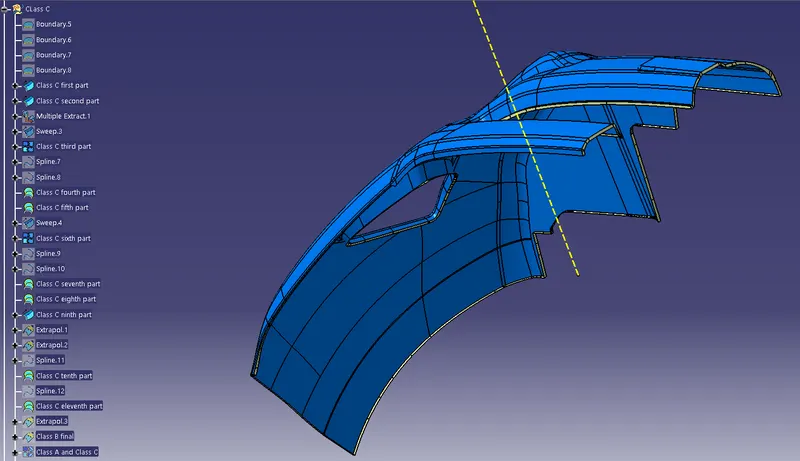
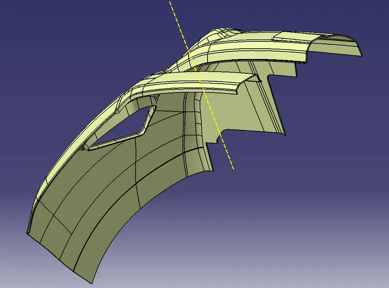
Then as per procedure, Class A and Class C are joined and trimmed with Class B and with the use of close surface command, solid body is created.
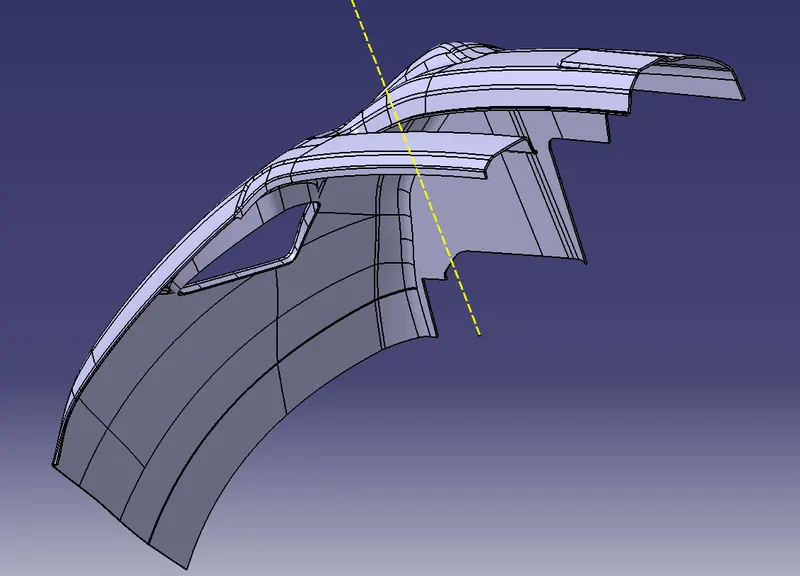
Plastic part draft analysis: -
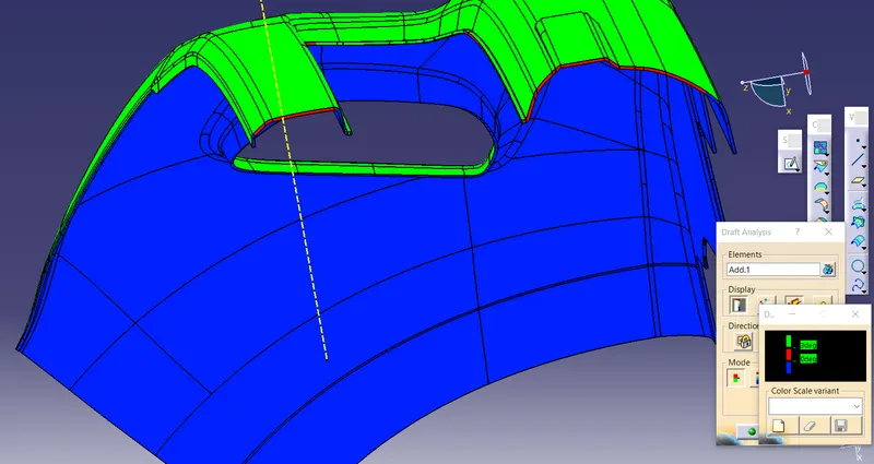
Observing the results of draft analysis, we can say that Class A and Class B give expected results with Class A having draft angle above 3-degrees and Class B having negative draft angle. But Class C is having parts which are red or blue. To resolve this issue, the sweep angle can be changed for the parts of Class C which are red or blue.
The sweep angle for the front faces of Class C is changed from 3 to 5-degrees. The sweep angle of the middle face of Class C is changed from 90 to 93-degrees.
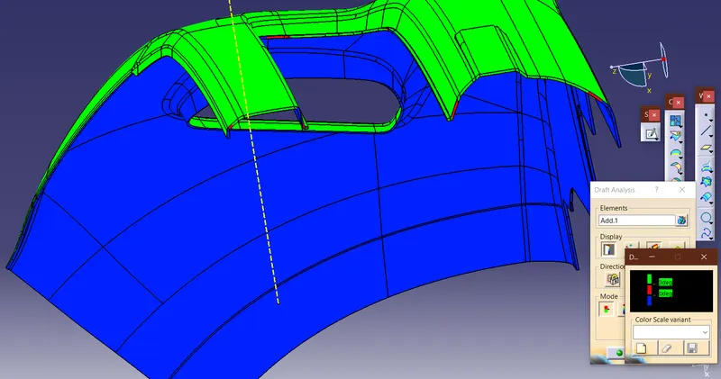
After doing draft analysis after the changes, we see that Class C near the front face now has draft more than 3-degree, thus it can be said that changing the draft angle and altering the multi-section surfaces adjoining the sweep will resolve the issue of the front faces. However, after changing the sweep angle of the middle Class C we see that regions have interchanged the colours i.e., the green part has become red and red part has become blue or green, thus, the issue has not been resolved.
Seeing the results it can be inferred to resolve this issue the middle boundary of Class C has to broken for each segment and given a different sweep angle to each segment to satisfy the draft condition which is a long and tedious process. Thus, given time, solution is possible for the current errors.
Various orientations of the part are given below
Isometric view
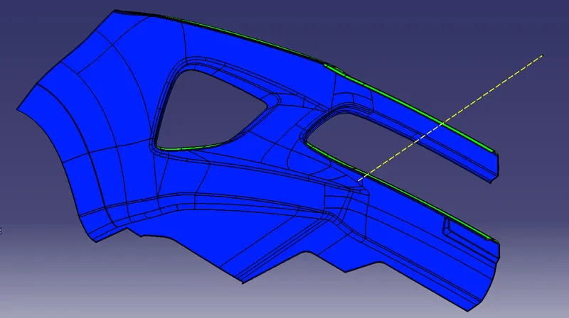
Front view
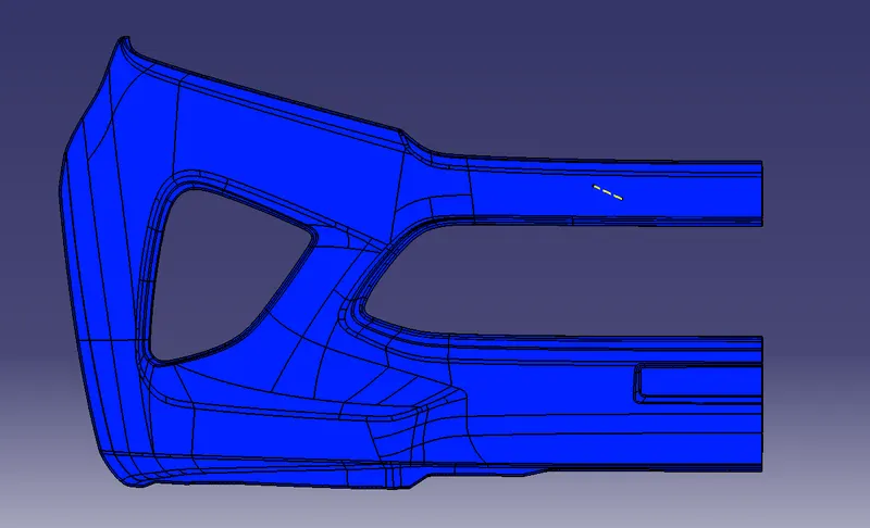
Top view
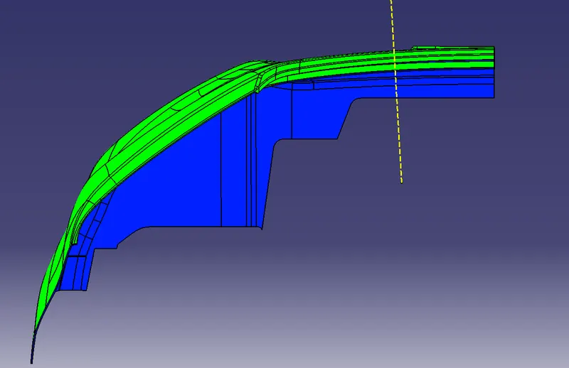
Left side view