Week 8 - Challenge 4 - Bumper
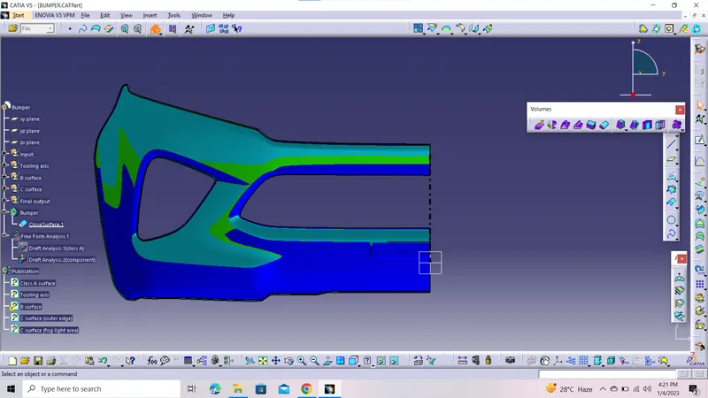
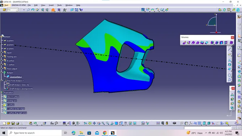
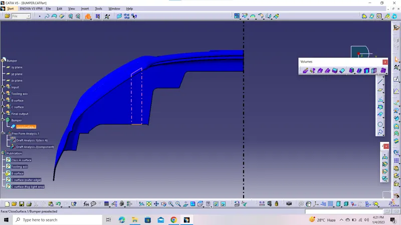
Creation of solid model of Bumper using given Class A surface of bumper and also to do draft analysis on both final solid model and also on given Class A surface.
Bumper: A bumper is a structure attached to or integrated with the front and rear ends of a motor vehicle, to absorb impact in a minor collision, ideally minimizing repair costs.The material used to manufacture a bumper should posses good toughness property.
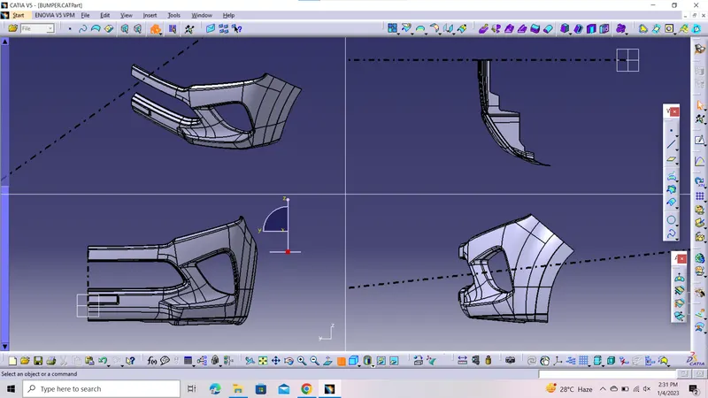
1)Steps followed to create tooling axis in this project:
- Here the bin type area have more coverage in bumper , so we can conclude that tooling axis is passing through the 2 extreame walls of bumper.
- Create an intersection curve along extreme vertical edge with reference to xy plane.
- Draw 2 lines along extreame ends.
- Make a bisector using extreme line entities.
- Draw 2 lines along the grill area walls .
- Make 2nd bisector with the line entities created along grill walls .
- Make another bisector using 1st and 2nd bisectors, and this is itself is the tooling axis of bumper.
2)Steps followed in this project to create Class B surface:
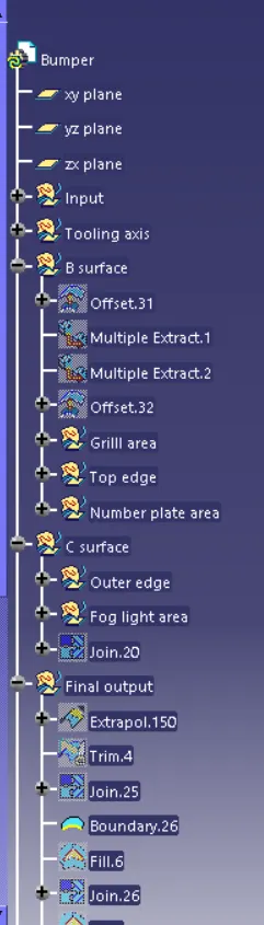
- Initialy, we offset the entire Class A surface at a distance of 3mm inwards.
- Check closely, that there is any unfilled or missed surfaces from Class A surface. If any, notice the surface. Here in the project, the surfaces adjacent to fillets at extreme top edges and also grill area are missing.
- Dissable the handicapped edges using Multiple extract with enabling Complimentary mode. Then extract the complete surfaces from class A surface and offset it to 3mm inward.
- Now , we got 2 different closed surfaces and now, we can proceed with assual procedure like, creation of boundary followed by extrapolating , trim and finally edge filleting.
3)Steps followed in this project to create Class C surface:
- Take Boundary of outside edges of bumper.
- Create Class C surface, using Sweep command with using surface reference.
4)Join the Class A and Class C surfaces.
5)Make sure that, the edges is intersecting properly and there is no intersecting edges is happening within Class C surfaces.
6)Join the class B surface with Class A and Class C.
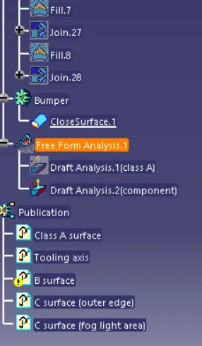
7)Insert a part body and change interface to part design and using THICNESS command create the soild model.
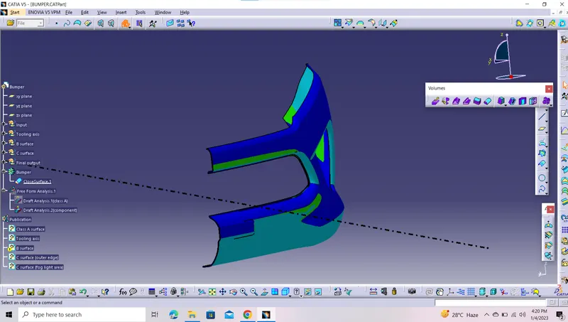
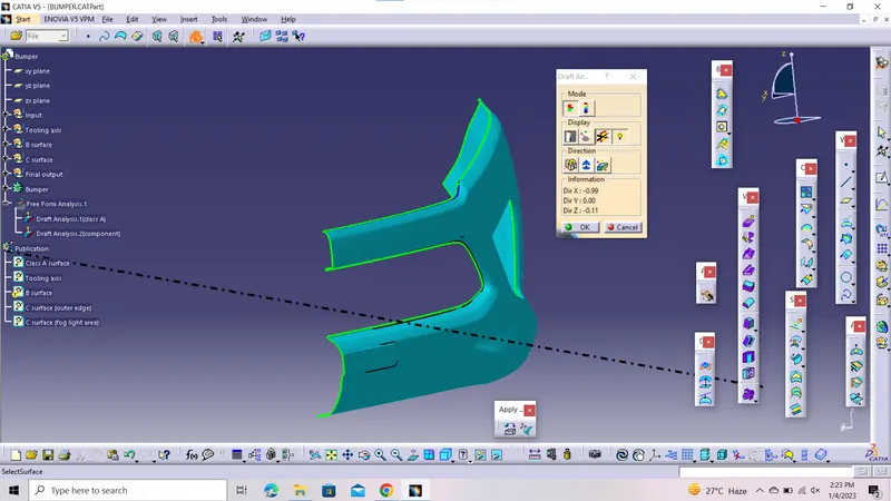
8)Steps followed to do draft analysis on classA and final output of bumper :
- Initally , change material mode .
- Place the Coordinate system on to the tooling axis .
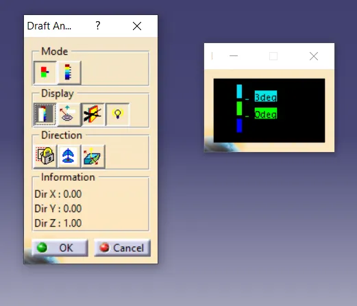
- Lock the position and set the draft angle range with proper color code.
- Select the solid model that needed to be drat analysed .
- In the same manner draft analysis is performed for Class A surface also.
9)Publications is also done for Tooling axis, Class A , Class B and Class C surfaces for easy accessible.