Week 8 - Challenge 4 - Bumper
AIM: To create the Bumper Plastic component through the given Class-A surface. To begin with, the tooling axis for the given
Class-A Surface should be created meeting the requirements of the draft angle and at the end perform the Draft analysis
on the model.
Take the Thickness of the component to be 3 mm.
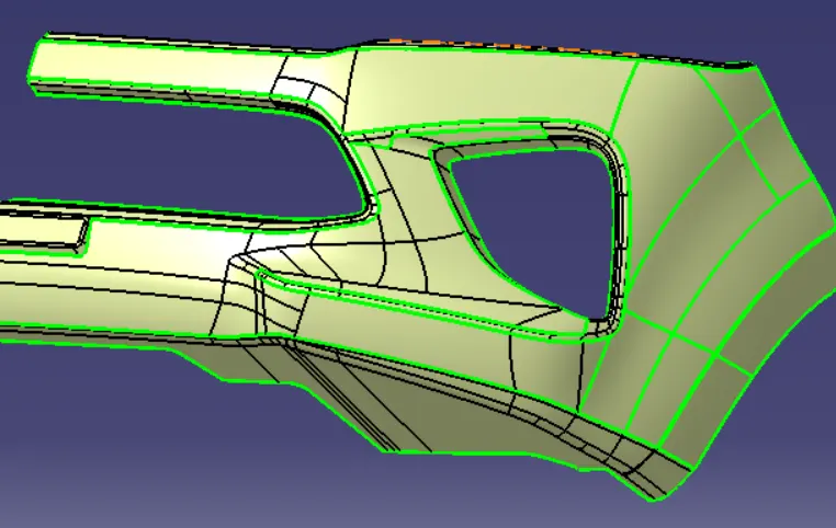
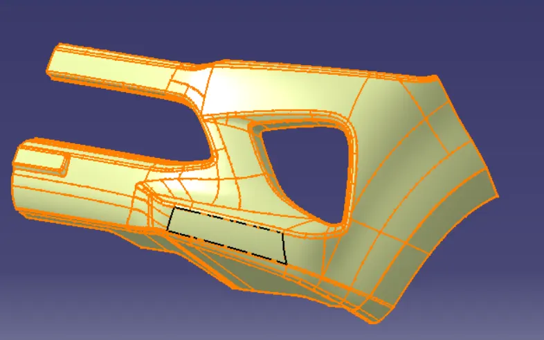
GIVEN CLASS A-SURFACE:
GIVEN SURFACE-A:
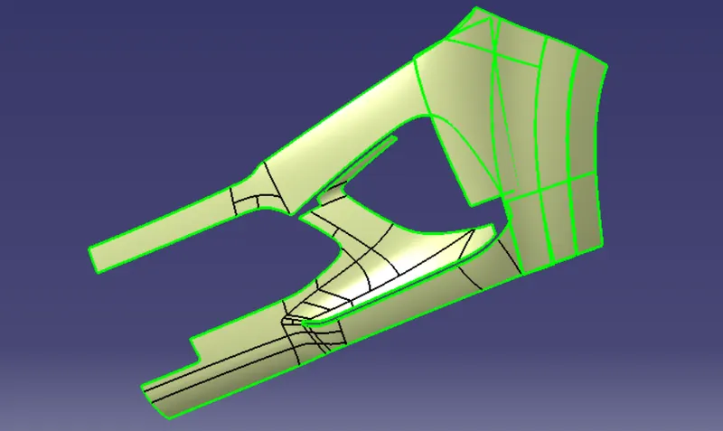
Design of BUMPER with the help of CATIA V5
Objective:
- To design BUMPER with respect to the class a surface.
- Create class b surface and class c surface and the tooling Axis
- Convert those class A surfaces in a close body and make it into the solid body provide the thickness of 2.5 mm
- Performing draft analysis to verify the creation of tooling axis and class C surface
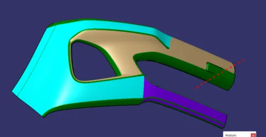
By creating tooling axs:
- Create a point at the base OR any flat surface from where we can se max no. of surfaces from the class A surface.
- Extend the line at that point which is perpendicular to the plane or surface
- Chane the colour of that line and make it as construction geometry
- Rename it as tooling axis.
To create surface of bumper:
- Select the whole class A surface and take an offset mode by 2.5mm at inside.
- Now you can see some gaps are present in the offset surface….
- You can fill those gaps by using multisection option, belnd option or by extracting the classA Surface.
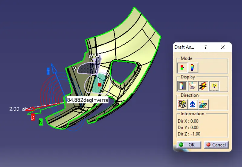
Draft analysis:
- Procedure of creating draft analysis
- Go to insert menu and select the analysis option
- Select feature and draft analysis
- Select the part option and select the surface
- Drag the compass and place on tooling axis
- make sure that the top surface is in green colour as draft angles should not exeed 3 degree.