Week 8 - Challenge 4 - Bumper
AIM:
Create the Bumper Plastic component through the given Class-A surface. Class-A Surface should be created meeting the requirements of the draft angle and at the end perform the Draft analysis on the model.
OBJECTIVE:
- To crate a tooling axis for the plastic component
- To create a Bumper of plastic component from given Class A surface.
- To perform the draft analysis over the plastic component.
IMPORTING THE MODEL
- Open the downloaded IGES file make it has class A surface by jioning all the surfaces
PROCEDURE:
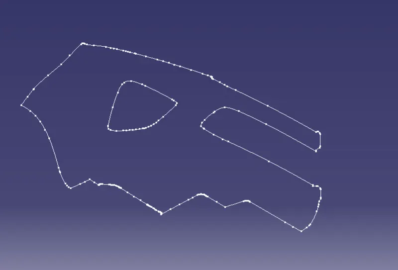
- Doing the continuity check to ensure whether given class A surface is continuos or not.By using Boundry/jion method,It seems there is no dis-continuos boundry
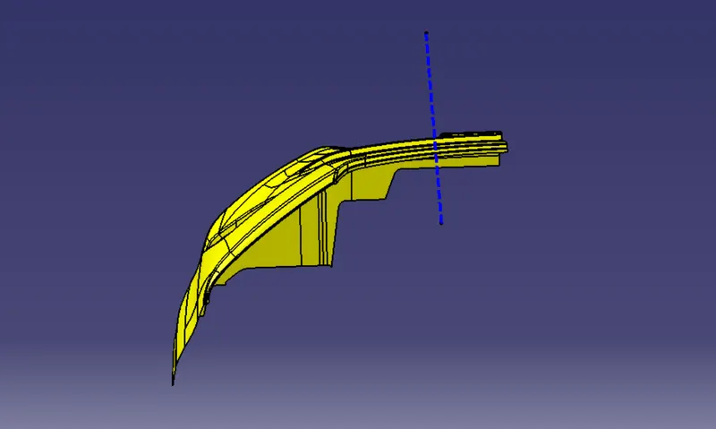
- create point on Class A surface plane & create tooling axis on point & normal to surface (On surface method)
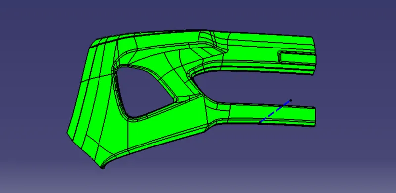
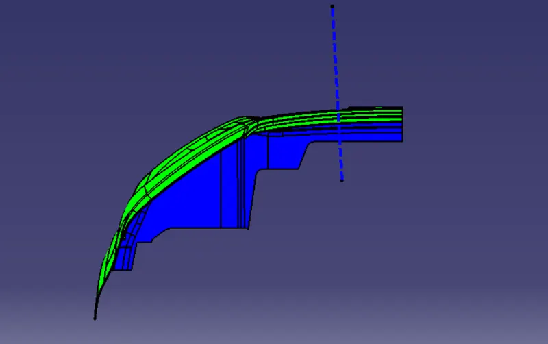
- Perform draft analysis on the given class A surface,Below pic shows the result of draft analysis,It cleares that it has 3^0 draft throughout the surface with respect to tooling axis as it is in green color
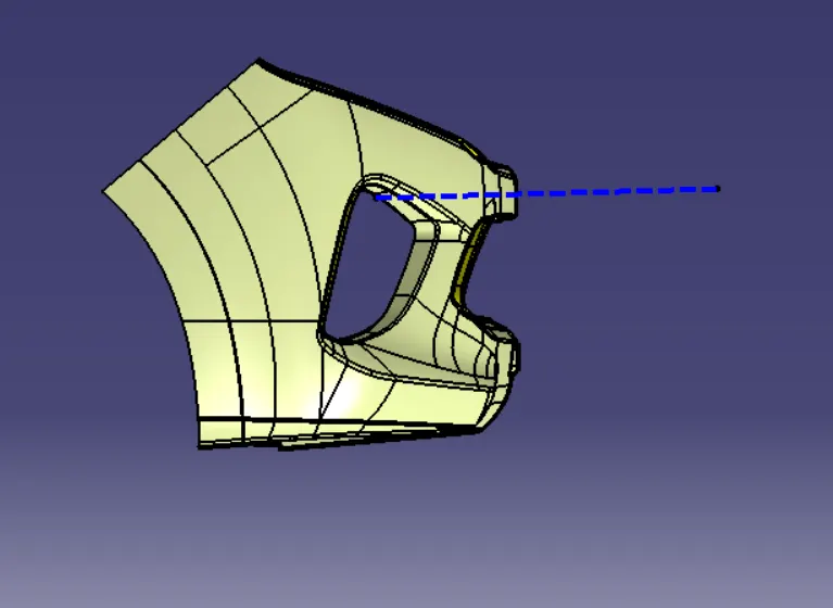
Creating Class B surface:
- In this component Directly offset class A surface to 3 mm
- Then repair the patches of class B surface
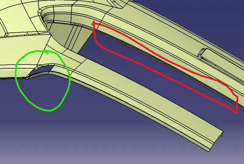
- To repair used the operations like multi surface,trim, jion etc with help of tools like line,spline obtain the class B surface
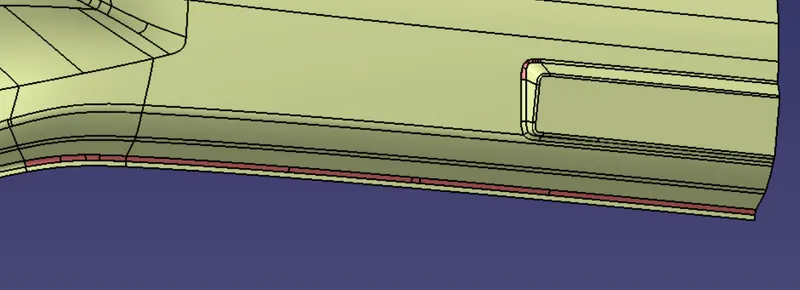
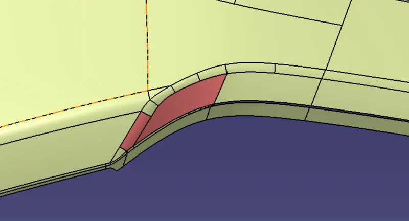
- Similarly did the above procedure for All the Patches
- The finle Class B
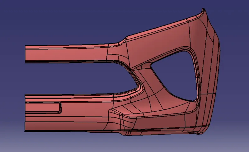
Creation of Class C:
- Extract all the boundry of class A surface Separately by observing the complexity ,Then sweep them
- Trim them together then we will get Class C surface
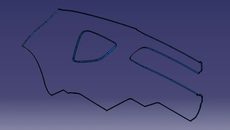
- Jion the class A & class C surface(by trimming)
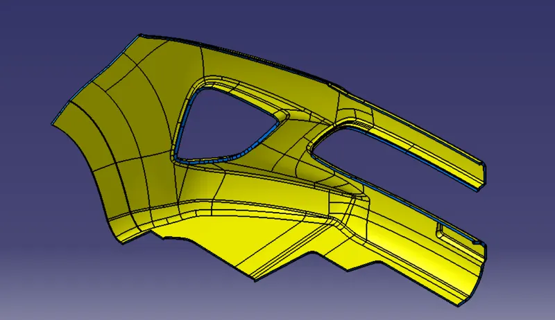
- Then jion all the Class A,B & C Surfaces
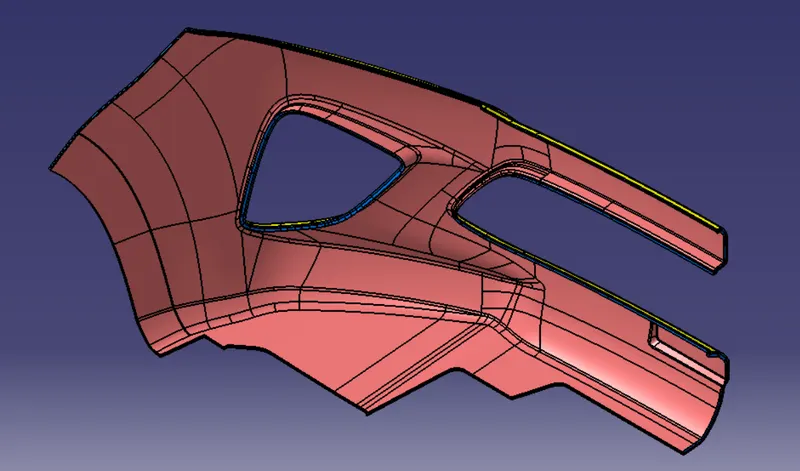
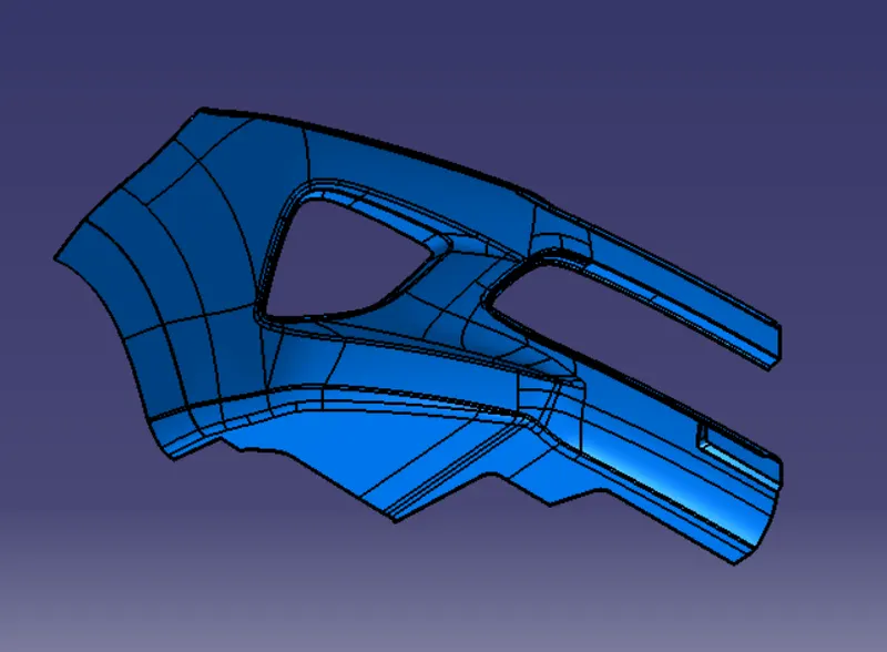
- Then convert this closed surface to part body in the part workbench,we will get the required Bumper plastic component
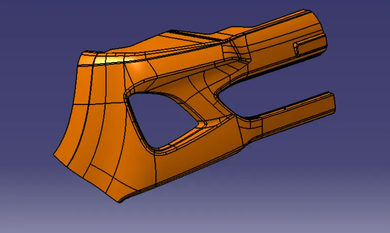
- perform the Draft analysis on the Finle model.
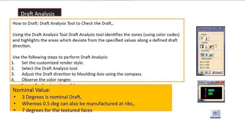
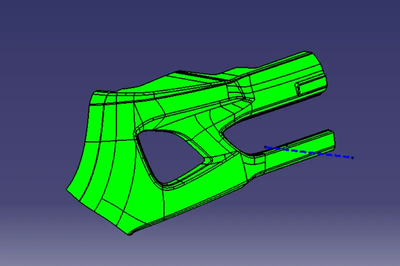
From the above figure we can observe it is satisfying 3^0 nominal draft
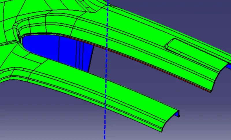
but at some corner it's satisfying 1.6^0 (refer below pic) it also manufacturableby taking some considerations
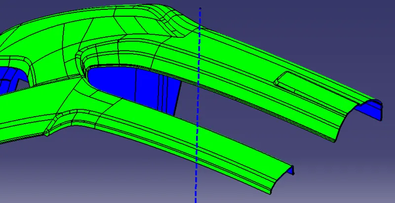
In some area of C surface it is blue too due to it's perpendicular Relation b/w A&B & it is also in negative side
Hence plastic component can be created
- solid model with the proper color code of the draft angle in various orientations
- green- 3^0
- Red- 0^0
- Blue- negative side & in this case in some area of C surface is also blue beacause it is having 90^0
- Isometric view
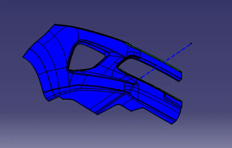
- Front view/Back view
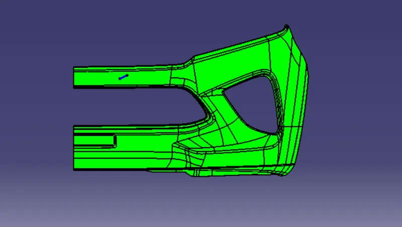
- Side view
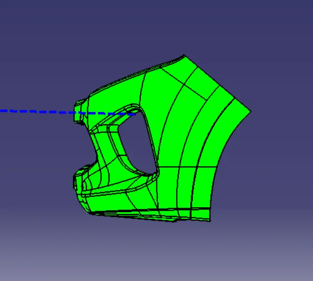
- Top view
CONCLUSION:
The Plastic Component is created & Draft analysis is Done