Week 8 - Challenge 4 - Bumper
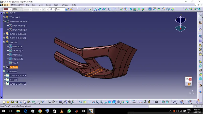
Aim: Create the Bumper Plastic component through the given Class-A surface. and create the tooling axis for the given Class-A Surface meeting the requirements of the draft angle and at the end perform the Draft analysis on the model.
The thickness of the component is 3 mm.
Design :
Insert the class A surface of the Bumper in CATIA software.
Determining the tooling axis for the Bumper
Creation of class B surface.
Creation of class c surface.
Join the bumper class A, class B, and class c surfaces and ensure all the surfaces are closed surfaces.
Use the Close Surface feature to make a solid body from the surface.
finally, Perform the Draft analysis on the bumper plastic component.
Creation of Tolling axis:
To create the tooling axis first we have to check the best suitable direction for tooling by using the compass. the x direction is suitable for creating the tolling axis because in the x direction most of the surfaces are clearing while performing draft analysis. Generally tooling axis is created using bisecting line method but here A line normal to the surface is created in the x direction and considered the tooling axis.
Draft analysis of Class- A
After creating a tooling axis we do the draft analysis. Before drafting we have to make sure that in the view mode it is selected for the materials.
After selecting the feature draft analysis tool we drag the compass from its position to the tool axis. Then lock the compass. After that select anywhere on the component and it will give you the result.
We change the minimum draft for the component to 3°.
We can use the running point option to check the angle of the component.
Closed surface of class b surface
Then trim the class-B surface to join (A+C) this will make sure that we get a closed surface. We can check it using the boundary tool, if it gives an error that means that the component is closed.
Then We go to the part design workbench and use to closed surface tool to create a solid body.
hence, we created our final plastic component.
Draft analysis of the final plastic component:
- Go to the Insert menu and select the Analysis option.
- Select Feature Draft Analysis.
- Select the Material option and select the surface.
- Drag the compass and place it on the tooling axis.
- click on the surface and see that the surface is within the permissible limit of the draft values.
- Click on Okay.
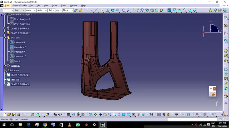
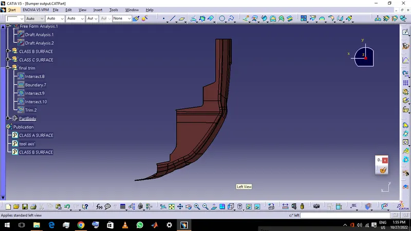
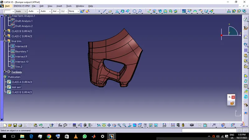
SCREEN SHOTS :