Week 8 - Challenge 4 - Bumper
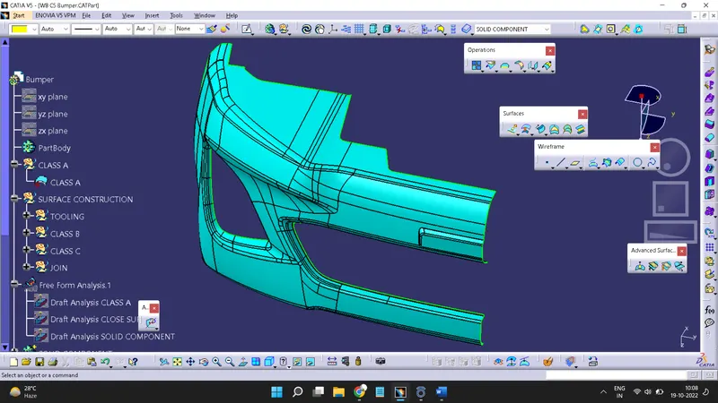
Objective:- Create the Bumper Plastic component through the given Class-A surface. To begin with, the tooling axis for the given Class-A Surface should be created meeting the requirements of the draft angle and at the end perform the Draft analysis on the model.
Introduction:-
A class A surface is our given data. By using this we need to create a CLASS B& CLASS C surface and after that by joining all of them Create a close surface.
METHODOLOGY:-
For creation of component need to use this steps:
Tooling axis
Draft analysis
Class-B surface
Class-C surface
Making a solid model from surface.
Following tools were used to reach the final step:
Extract
Un-trim
Trim
Extrapolate
Offset
Edge fillet
Boundary
Sweep
Join
Close (part design)
Creation of Tooling Axis:-
A tooling axis is the direction of a component where the component is easily ejected from core and cavity in a particular direction. A tooling axis is a most important for removing material with very finished surface.
Before start working and any component it is needed to create a tooling axis firstly
First of all analyse a component for best tooling axis
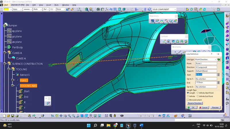
After analyse extract a one surface from class A.
By use that surface & create a point on it.
Use Line with point-Direction and create a line.
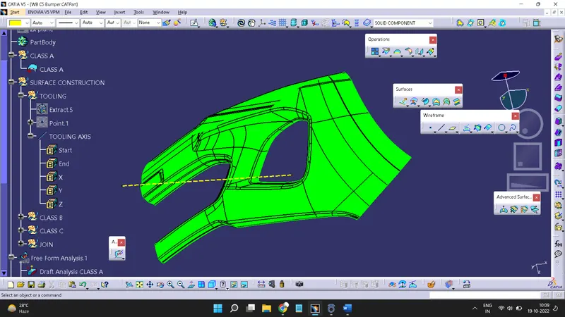
Do a Draft analysis on Class A and see a result.
If every surface is looking good so take this line as Tooling axis
Draft Analysis on CLASS A:
Creation of Class B Surface:
For creation of Class B no need to do a same procedure we done before.
For creation of Class B Surface take offset with give thickness of component inside the Class A
The surface which create have some intrups....
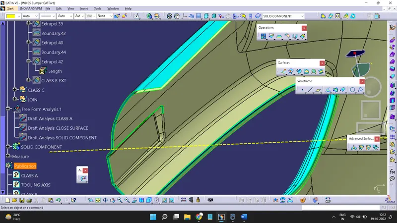
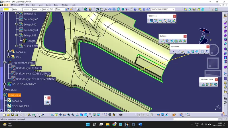
So only need to solve by using different tools.
& Create Class B.
After creation of Class B do extrapolate all the outside edge it will help for get intersection easily with class C& Class B.
&This will final Class B Surface.
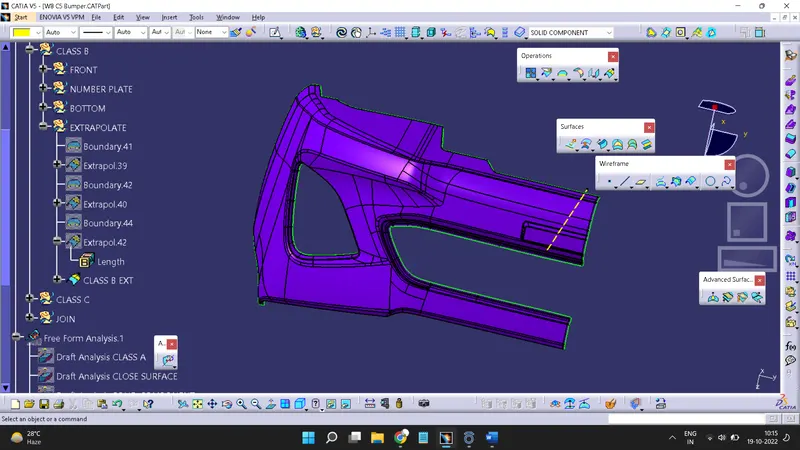
Creation of Class C Surface:
Firstly Analyse the component class C surface.
There is 2 type class C surface can be-
- Parallel to tooling axis
- Perpendicular or with some angle to tooling axis
In this challenge need create class c surface in perpendicular direction with some angle to tooling axis.
Now create a boundary with limits.
Use a sweep tool for creation of surface
Take limited length with angle 90°-93° .
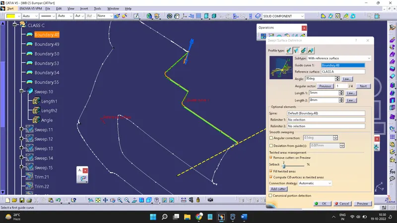
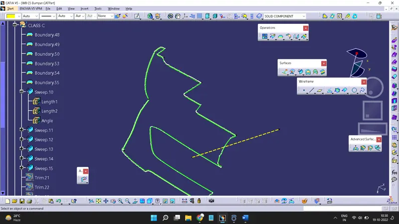
Create all surface for class C and now use a trim to Remove unwanted surface.
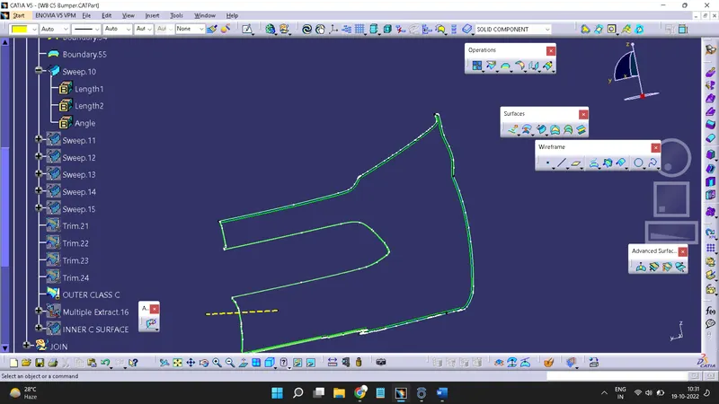
This is Final Outer Class C surface
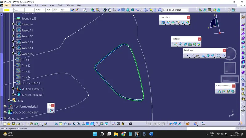
Same as create a inner boundary using multiple extract and do sweep
Creation of Close surface:
Firstly join the CLASS A & Inner Class C
then join it with Outer Class C surface & this will final Surface of Joining of Class A+C
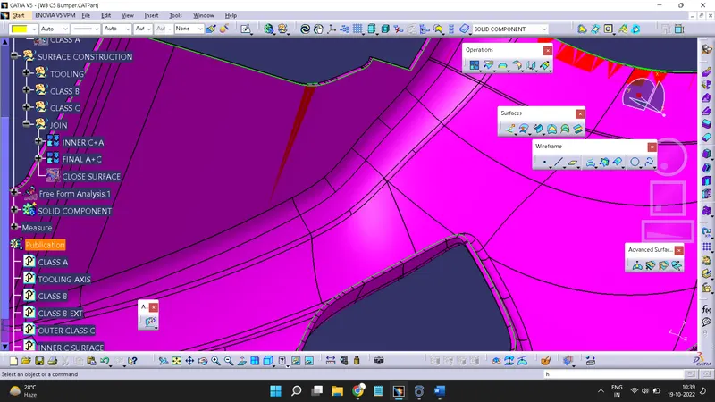
This is Final Close Surface
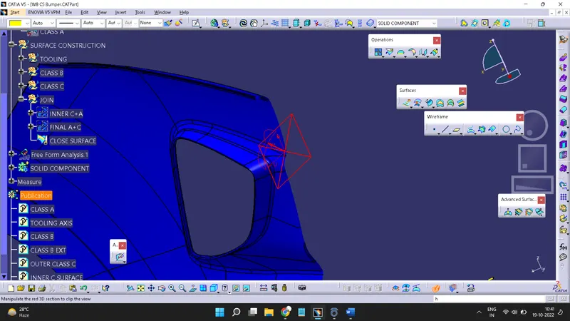
CREATION OF SOLID COMPONENT:-
goto Start>Mechenical Design> Part Design
Surface Based Features> Close Surface> Select close surface>OK
& hide surface
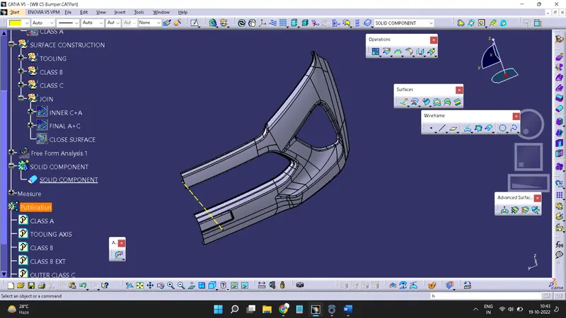
DRAFT ANALYSIS:-
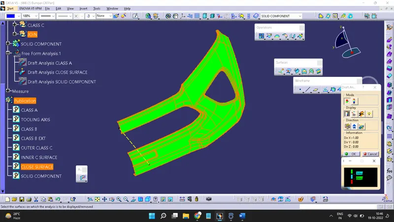
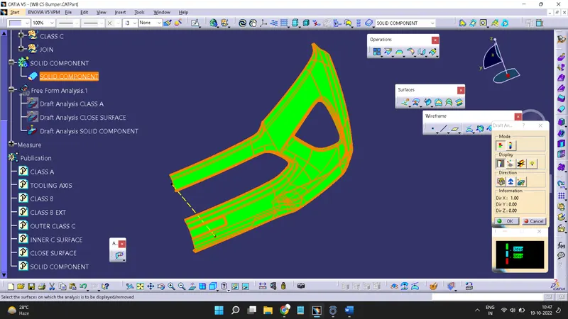
A draft analysis is helps to detect a angle of a component. it will be easily removed. In catia a draft analysis is performed based on colour rain identify zones Using a draft and by using a draft analysis we can verify taper angle.
Examine angle change with a face as well as look at what time line and injection surface in parts
A draft analysis help to give a proper draft angle
Draft angle describe the amount of taper of mould which perpendicular to the party line
Minimum draft angle is required 3 degree.
DRAFT ANALYSIS of class A surface:-
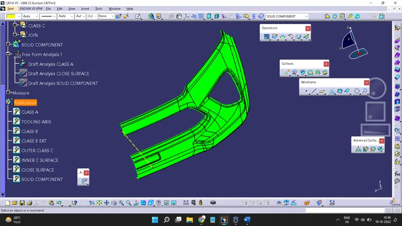
DRAFT ANALYSIS of close surface component:-
DRAFT ANALYSIS of solid component:-
Creation Of Publication:-
Goto tools> Publication
Select Component which need to Publish then OK.