Week 8 - Challenge 4 - Bumper
Week 8- Challenge 4- Bumper Design
AIM- The main aim of this challenge is to create a solid body of 'Bumper' with the help of the closed surface method by using the 'Generative shape design' workbench in CATIA V5.
REQUIREMENTS -Create the Bumper Plastic component through the given Class-A surface. To begin with, the tooling axis for the given Class-A Surface should be created meeting the requirements of the draft angle and at the end perform the Draft analysis on the model.
Take the Thickness of the component to be 3 mm
OBJECTIVES-
- Designing bumpers according to automotive industry Standard.
- Generate tooling axes for a given CLASS-A surface.
- Create surfaces of classes B and C
- Using part design workbench creating the solid body using close surface of A+B+C surface
- Perform draft analysis for both Class-A surface and Final part body.
INTRODUCTION TO BUMPER
A vehicle's front and rear bumpers serve two major functions: first, to absorb the energy created by these sorts of slow-speed accidents, and second, to safeguard expensive components including the main engine components, radiators and linked engine cooling mechanism, headlights, taillights, etc.
According to current design standards, the bumper structure of contemporary cars is made out of a reinforcing bar covered in plastic that is either composed of steel, aluminium, fibreglass composite, or plastic. The majority of current cars have bumpers composed of PC/ABS, a material blend of polycarbonate (PC) and acrylonitrile butadiene styrene (ABS).
DESIGN METHODOLOGY
CLASS A SURFACE – Applications for computer-aided industrial design are used to create Class A surfaces. In the business, Class A surface modellers are sometimes known as "digital sculptors." The A-Surface, the tangible surface that the end user can feel, touch, see, and so forth, is how industrial designers build their design aesthetic. Once we receive Class A surface, we need to create tooling axis for draft analysis
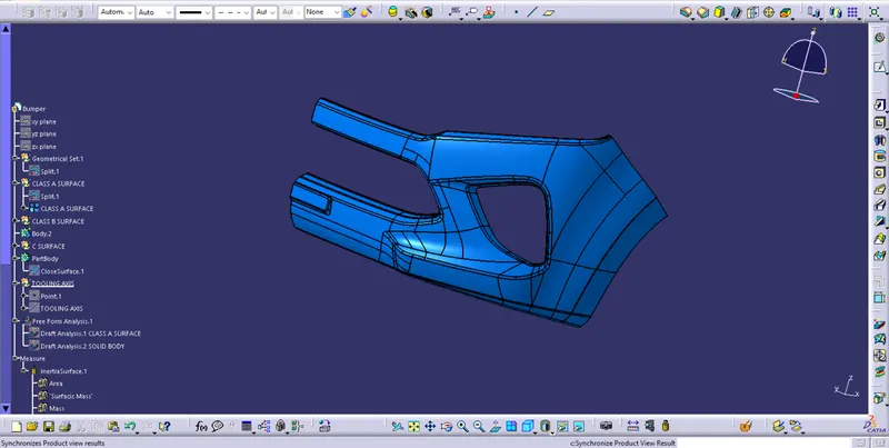
Tooling axis: The direction in which the mold or core and cavity opens is the tooling axis.
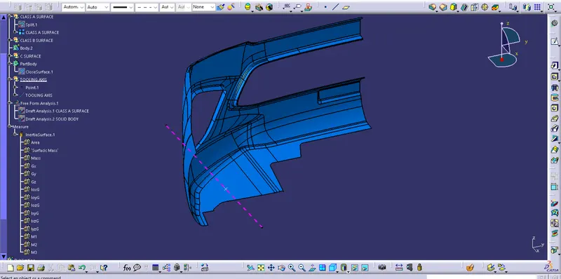
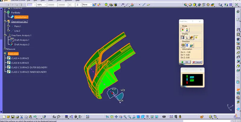
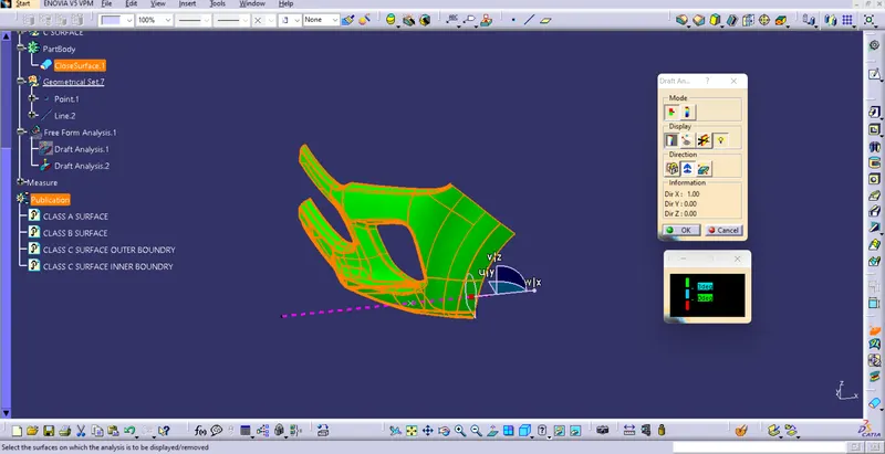
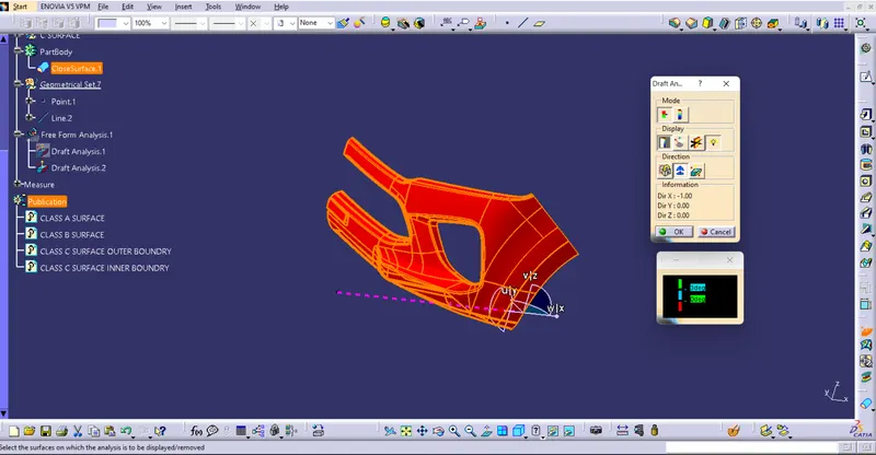
Draft Analysis of Class A-The draft analysis approach is used to determine our CAD model is capable to manufacture. The part should easily removeable from the dies. Generally the 3 degree of draft is maintain by the industries. In the below image we can see the part is successfully passing the draft analysis at given tooling direction.
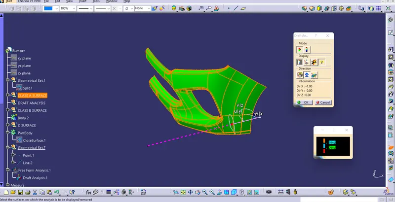
Class B surface - The Class B finish is a quality finish with only minimal imperfections. It does not required higher asthetic look. It is used as a housing the the attachments. Class b surface is created by offsetting the class A surface. While creating class B surface some of the feature remain unoffseted such as fillets that we need to create using extrapolate, untrim, split, multi-section surface and trim command.
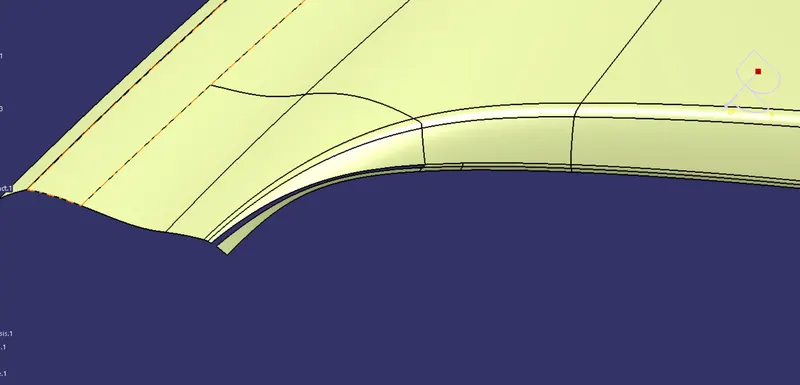
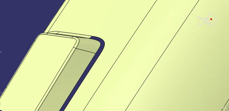
Class B Surface
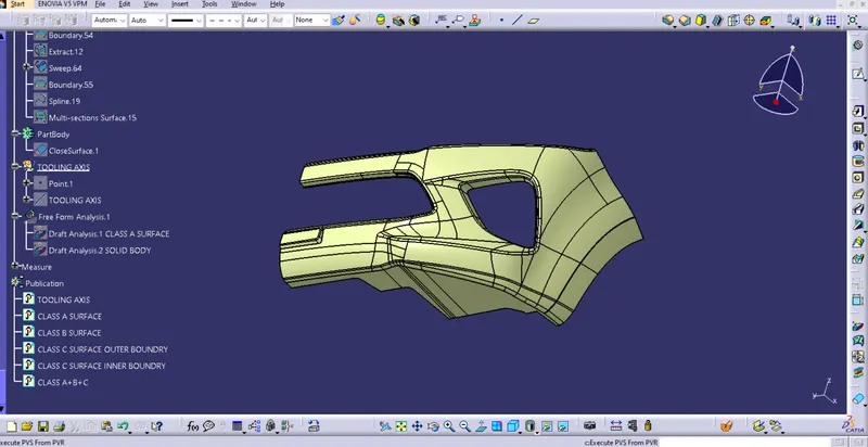
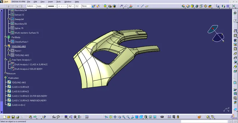
Class C surface – Class C surface is used to connect Class A and Class B surface. Class C surface is created by sweep command. By creating the boundary of Class A surface using sweep command (Profil type – Line, Subtype- with reference surface ) we can create class C surface
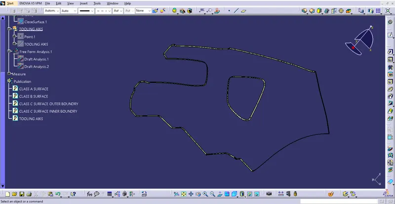
Once the Class C surface created we need to Join Class A +B and Trim to Create Class A+B+C
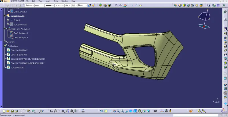
SOLID BODY CREATION -To create the solid body insert a part body in part design workbench and select the A+B+C surface using close surface feature
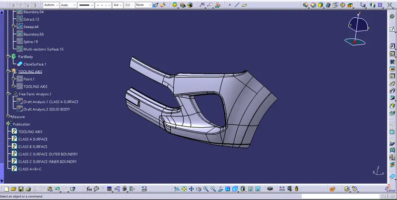
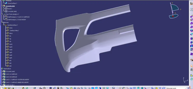
Draft analysis of Solid body-