Week 8 - Challenge 2 - Switch Bezel Design
TOOLING AXIS
By considering this tooling axis, the draft angle needed for the opening and closing of the molds can be determined.
We can create a tooling axis by using the bisecting method.
The purple doted line indicates the tooling axis.
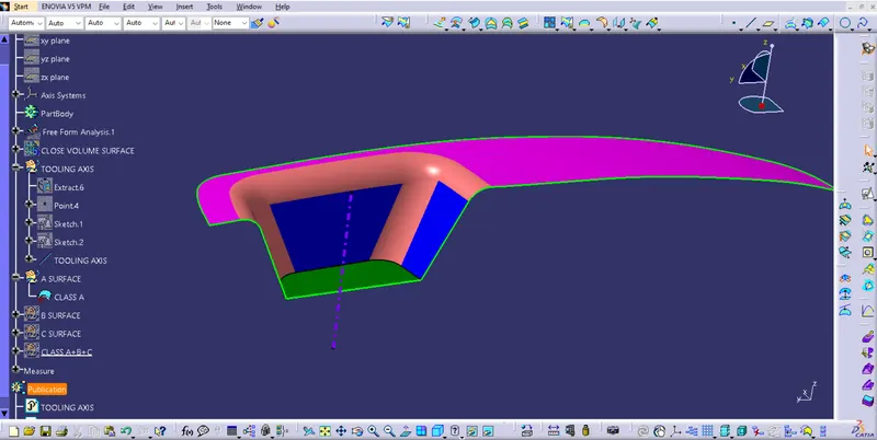
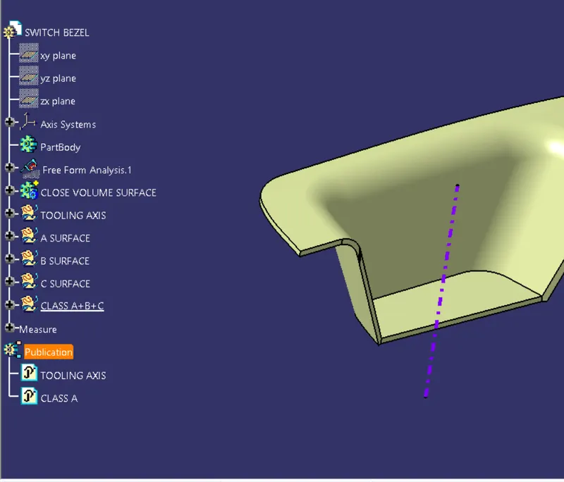
Tree structure of Switch Bezel modle
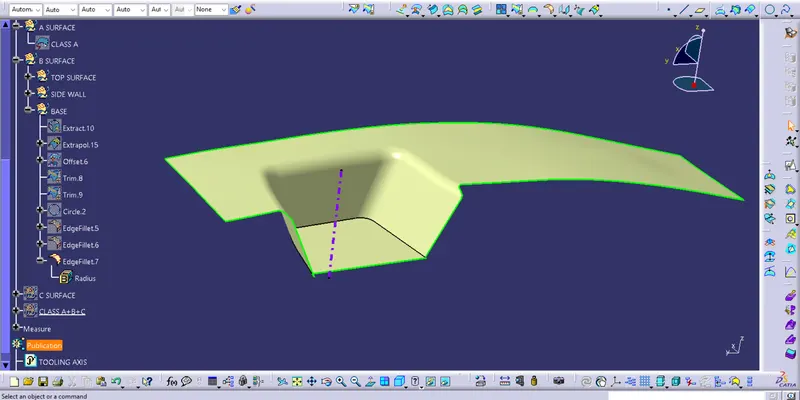
Class B surface
Class B surface designed from class surface by extracting the class A surface, Untriming it , Extrapolating it and offseting extrapolating surface then triming the exes surfacing.
Class C surface
The class C surface is used to connect class A and Class B surfaces. By applying boundary to the class A surfacing and using sweep with the draft direction the class C surface was formed.
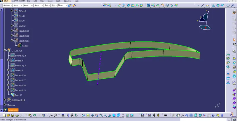
Class A+B+C surface
Class A+B+C surface is joined using join commant to make one complete surface
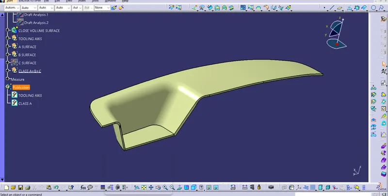
Close body Surface
The surface is converted into part body using close surface .
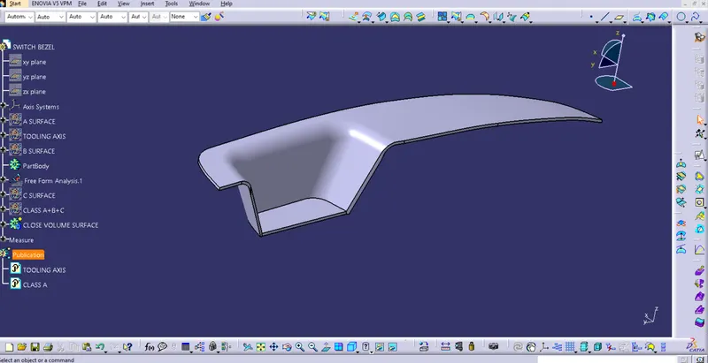
Draft analysis
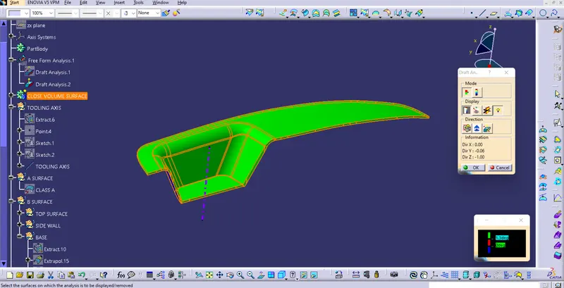
Draft is a tapered portion provided on the part for easy removal of the component from the mold during manufacturing. Plastic components with complex shapes are particularly subject to this process. It is generally provided that the draft angle is 3 degrees, but it can vary depending on the design of the component.
And it was found that the surfaces were not clearing 3 degree draft angle initially applied.
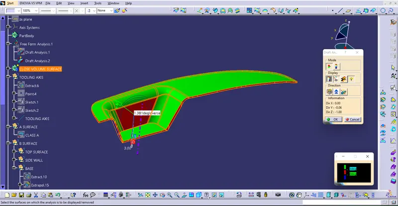
As a result, the bar was set at a lower draft angle of 1.3 degree and the surfaces cleared the given draft angle.